Manitowoc Published 09-09-16, Control # 229-09 10-67
MLC650 SERVICE/MAINTENANCE MANUAL ACCESSORIES
ACTIVE FIXED MAST STOP SYSTEM
General
This part of Section 10 provides the electrical and hydraulic
control of the active fixed mast stop (AFMS) system.
Additional component information for this system can be
found in the following sections of the Service Manual:
• Section 2: Hydraulics
• Section 3: Electrical
See Figure 10-54
for an illustration of the active fixed mast
stop.
See Figure 10-60
for the hydraulic schematic of the AFMS
system circuit.
See Figure 10-61
for the electrical schematic of the AFMS
system circuit.
The AFMS system consists of two fixed mast stops, each
containing an integral hydraulic cylinder. The AFMS system
controls the pressure within the mast stop cylinders over the
operational range of the cylinder as well as adapts to current
crane conditions.
Each mast stop cylinder contains the following internal
components:
• Hydraulic accumulator
• Pressure relief valve with bypass check valve
• Rupture disc
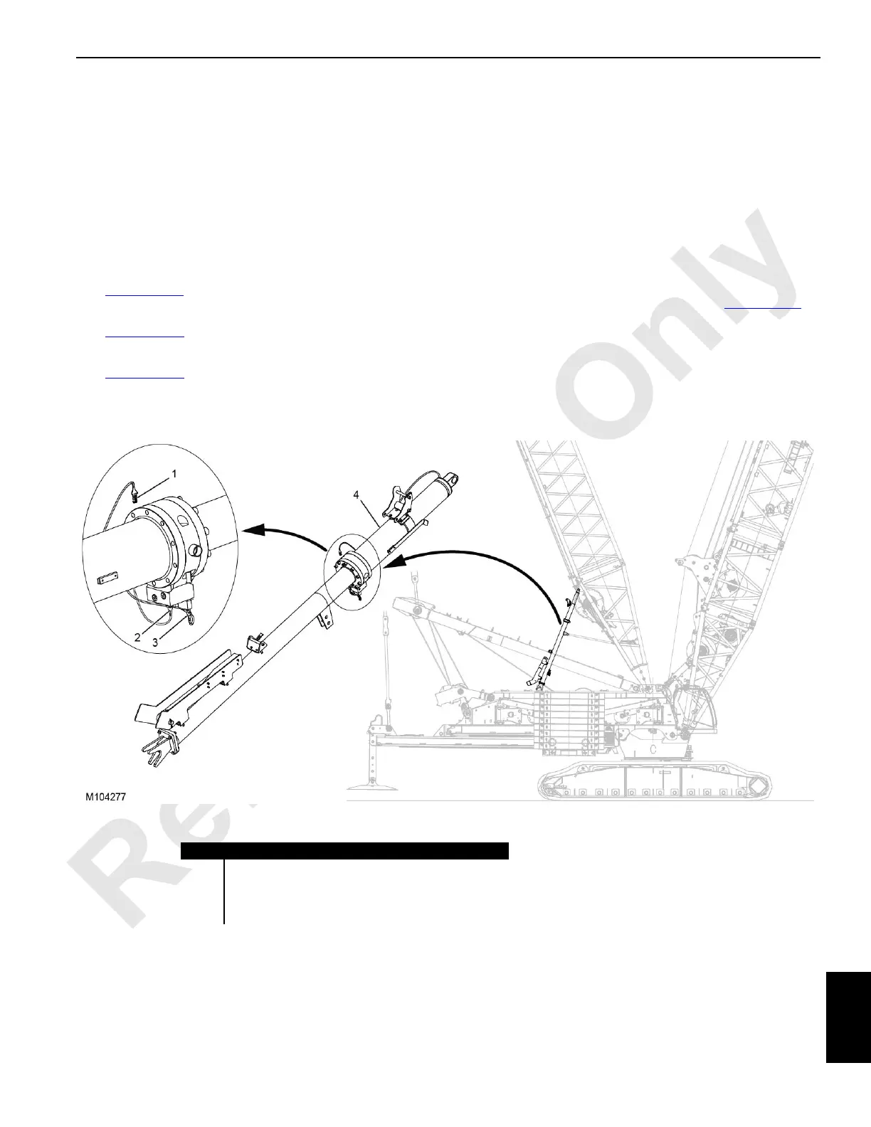
Each mast stop also uses the following (see Figure 10-54
):
• Mast cylinder pressure transducer (1)
• Mast cylinder pressure-reducing solenoid valve (2)
• Mast cylinder directional control solenoid valve (3)
• Direct acting relief valve
Item Description
1 Mast Cylinder Pressure Transducer
2 Mast Cylinder Pressure-Reducing Solenoid Valve
3 Mast Cylinder Directional Control Solenoid Valve
4 Mast Stop with Integral Hydraulic Cylinder
FIGURE 10-54