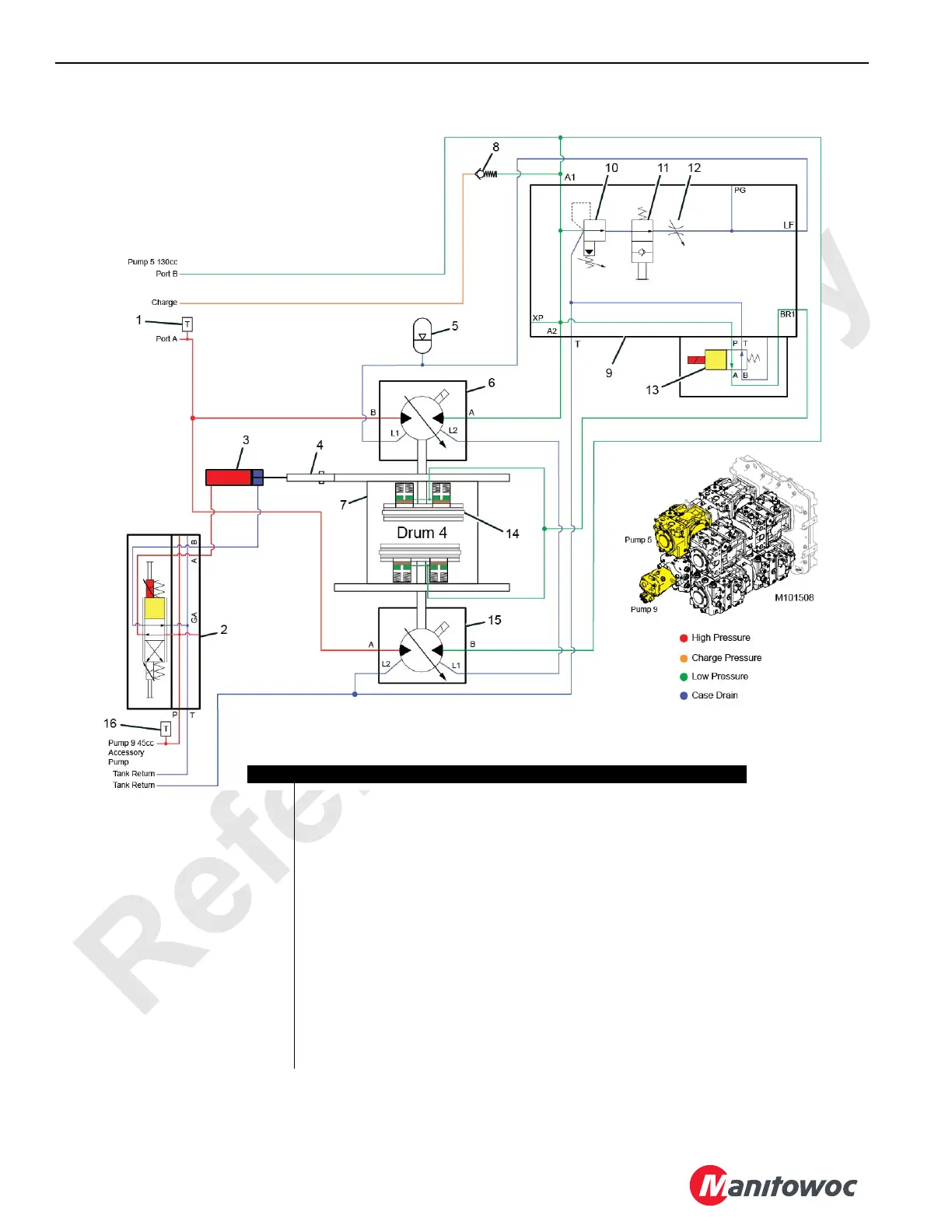
FIGURE 5-14
Item Description
1 Pump 5 Pressure Transducer (drum 4 psi)
2 Pawl Solenoid Valve Control Manifold
3 Drum Pawl Actuator
4 Drum Pawl Assembly
5 Accumulator
6 Drum 4 Right Hydraulic Motor (variable 160 cc)
7 Drum Hoist Gearbox and Brake Assembly
8 Check Valve (0,35 bar [5 psi])
9 Loop Flushing Valve (6 GPM at 200 psi)
10 Pilot-Operated Sequence Valve (balanced piston)
11 Manually Operated Service Valve (2-position 2-way poppet control)
12 Flow Control Valve (6 GPM)
13 Drum Brake Release Solenoid Valve (2-position 4-way directional control)
14 Drum Brake Pressurized (disengaged)
15 Drum 4 Left Hydraulic Motor (variable 160 cc)
16 Pump 9 Pressure Transducer (acc systems psi)