Manitowoc Published 09-09-16, Control # 229-09 5-21
MLC650 SERVICE/MAINTENANCE MANUAL HOISTS
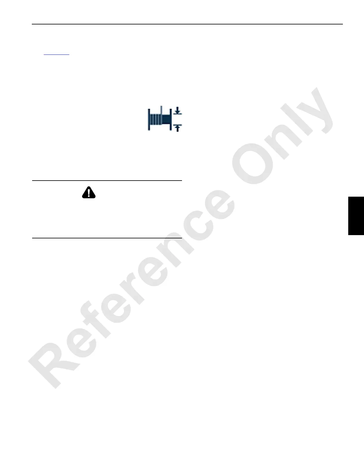
Drum 3 Minimum Bail Limit
See Figure 5-9 for the following instructions.
The optional minimum bail limit assembly on drum 3 is a
protective device that limits how much wire rope can be
spooled off the drum.
The minimum bail limit automatically stops the drum when
there are three to four wraps of wire rope remaining on the
first layer.
When the limit is reached, the operating limit
fault is activated and the fault icon appears in
the fault bar of the main display working
screen.
NOTE: The drum can be operated in the hoist direction
when the minimum bail limit switch is contacted.
Field adjustment should not be necessary unless a new limit
switch is installed.
Lowering Limit Switch Replacement
Removal
1. Land the load from the drum being adjusted.
2. Lockout-tagout the crane.
3. Remove the fasteners (3) and remove the switch cover
(2).
4. Remove the cable restraint connector (4) and carefully
pull the electrical wires from the limit switch assembly
(1).
5. Remove capscrews (5), washers (6), and the limit switch
assembly.
Installation
1. Connect the electrical wires to the new switch as follows.
a. Remove the switch cover (2).
b. Connect the electrical wires and tighten the cable
restraint connector (4) onto the switch cover.
c. Install the switch cover.
2. Using capscrews (5) and washers (6), install the limit
switch assembly (1).
Adjustment
1. Adjust the rope so that there are three wraps on the first
layer of the drum (7).
2. Remove the cover (2) from the limit switch assembly.
3. Turn the limit switch adjustment screw (8) until the
switch activates.
4. Confirm the indication on the appropriate cab display.
5. Spool the rope on the drum (7) until there are ten wraps
on the first layer.
6. Spool the rope off the drum to verify the lowering limit
switch activates with three to four wraps on the first
layer. Adjust the switch, if necessary. Install the cover.
Weekly Maintenance
1. Check the lowering limit switch for proper operation. Pay
out wire rope from the drum. The drum must stop with
approximately three to four wraps of wire rope remaining
on the first layer.
2. Make sure that all electrical cable connections are
secure and undamaged.
3. Make sure that the capscrews holding the limit switch
assembly are tight.
WARNING
Falling Load Hazard!
Avoid possible injury. Do not operate the drum with less
than three or four full wraps of wire rope remaining on the
drum. Doing so can cause the wire rope to be pulled out of
the drum and the load to fall.