Manitowoc Published 09-09-16, Control # 229-09 5-61
MLC650 SERVICE/MAINTENANCE MANUAL HOISTS
BLOCK LEVEL
Operation
The block level sensors ensure that the load block remains
level when two load lines—drums 1 and 2—are routed to the
load block. Located on the #680 boom top, the sensors
monitor sheave rotation speed. The crane’s control modules
use signals from the sensors to equalize the rotation speed
of the drums so the load block remains level.
The sensors are adjusted at the factory and need to be
adjusted only when a new sensor is installed or the position
of a sensor is reconfigured.
Sensor Replacement
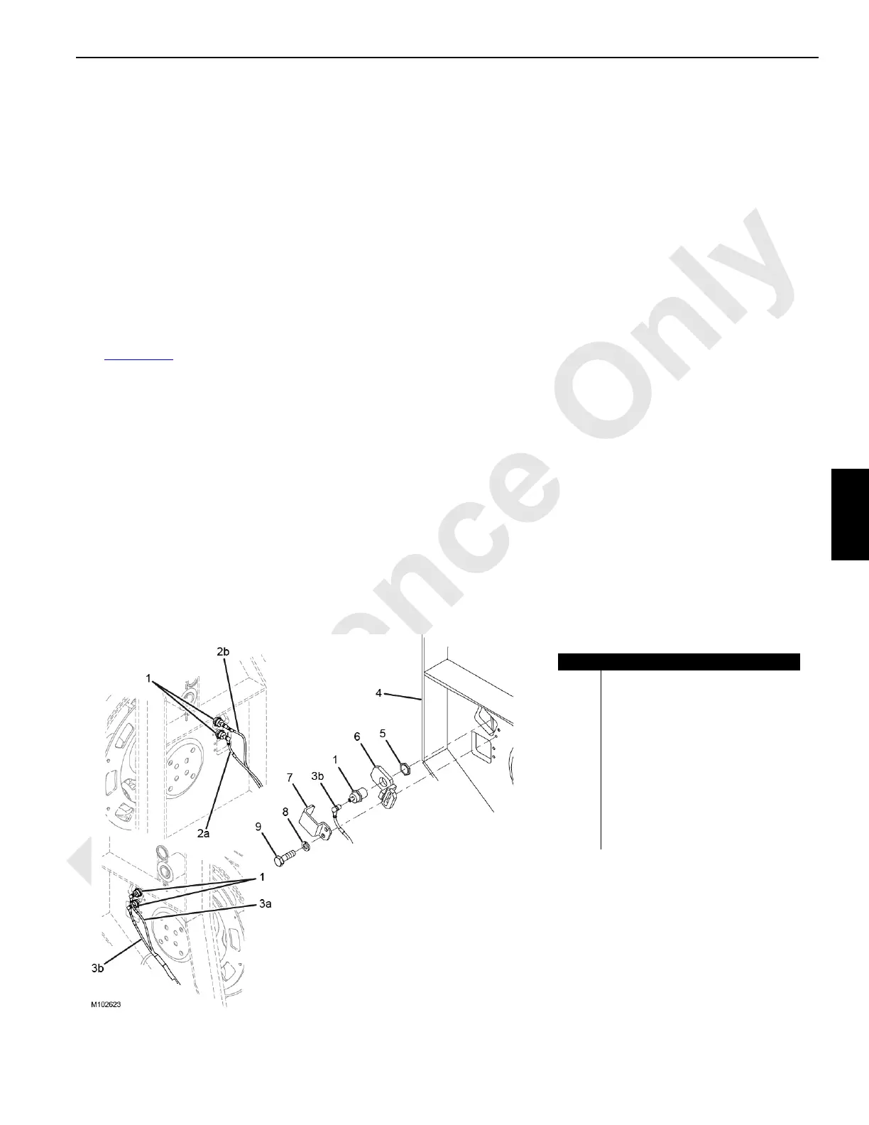
See Figure 5-32 for the following procedure.
Drum 1 and Drum 2
1. Lower the boom onto the blocking at the ground level.
2. Lockout-tagout the crane.
3. Remove the bolts (9) and washers (8). Remove the
cover (7).
4. Disconnect the electrical cable from the proximity
sensor (1).
5. Remove the jam nut (5) securing the proximity sensor
from behind the bracket (6).
6. Remove the old proximity sensor from the bracket and
install the new proximity sensor. Secure the new
proximity sensor with the jam nut.
7. Connect the electrical cable to the proximity sensor.
8. Insert the bracket into the rectangular slot of the guide
wire rope assembly (4).
9. Install the cover with the bolts and washers on the
bracket.
Adjustment
1. Loosen the jam nut (5) securing the proximity sensor (1)
to the bracket (6).
2. Turn the proximity sensor in or out as needed until the
gap between the end of the proximity sensor and the
proximity sensor target plate is 6 to 9 mm (1/4 to 23/64
in).
NOTE: The LED on the proximity sensor illuminates when
the sensor detects the passing target plate.
3. Tighten the jam nut.
4. Check for proper operation without load. Drums must
operate at the same speed and the load block must
remain level.
5. Readjust the proximity sensor as required.
Weekly Maintenance
1. Thoroughly clean the accumulated air dust on the
proximity sensor.
2. Make sure all proximity sensor assembly parts, wiring,
and connections are secure and undamaged.
Item Description
1 Proximity Sensor
2a Drum 1 Proximity A Cable
2b Drum 1 Proximity B Cable
3a Drum 2 Proximity A Cable
3b Drum 2 Proximity B Cable
4 Guide Wire Rope Assembly
5Jam Nut
6 Bracket
7Cover
8 Washer
9Bolt
FIGURE 5-32
Drum 1
Drum 2