Manitowoc Published 09-09-16, Control # 229-09 3-5
MLC650 SERVICE/MAINTENANCE MANUAL ELECTRICAL SYSTEM
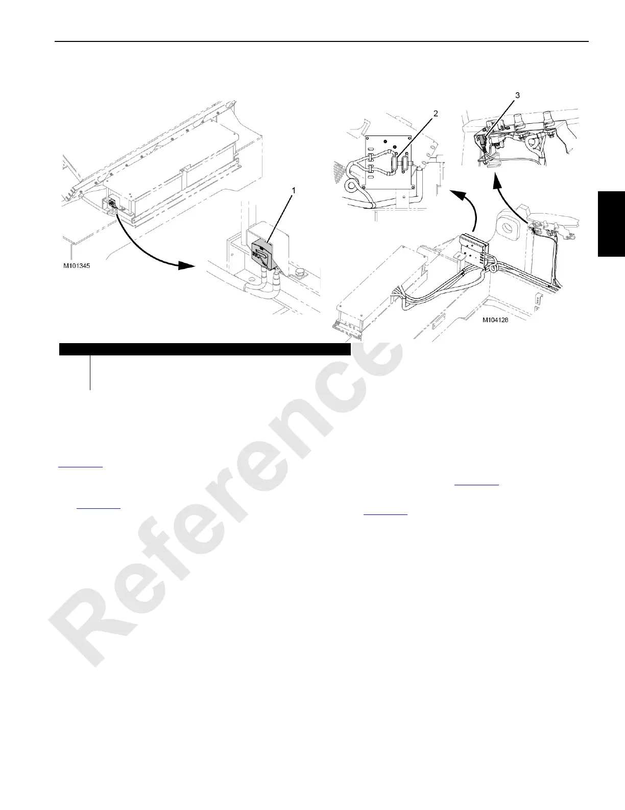
CIRCUIT BREAKERS, FUSES, AND RELAYS
For past production Tier 3 cranes, the alternator circuit
breaker CB0 (1) is mounted next to the battery box
(Figure 3-3
).
For Tier 4 cranes and current production Tier 3 cranes, the
alternator fuse F0 (2) is mounted on a panel left of the battery
box (Figure 3-3
).
The TCU CraneStar fuse F5 (3) is mounted on the battery
disconnect bracket.
All other circuit breakers and fuses are mounted in the
junction box DC load center (Figure 3-5
).
All relays are also mounted in the junction box DC load
center (Figure 3-5
).
Item Description
1 CB0—Alternator 150 A Circuit Breaker (Tier 3—Past Production)
2 F0—Alternator 150 A Fuse (Tier 4 and Tier 3—Current Production)
3 F5—TCU CraneStar 5 A Fuse
FIGURE 3-3