ACCESSORIES MLC650 SERVICE/MAINTENANCE MANUAL
10-32
Published 09-09-16, Control # 229-09
SELF-ASSEMBLY CYLINDER (OPTIONAL)
General
This part of Section 10 provides operational information and
electrical and hydraulic schematics for the self-assembly
cylinder.
Additional component information for this system can be
found in the following sections of the Service Manual:
• Section 2: Hydraulics
• Section 3: Electrical
The self-assembly cylinder is controlled by the following
methods:
• Setup remote control
• J4 joystick (located on the right console in the cab)
• Manual control lever (located on mast assist and self-
assembly cylinders valve assembly) (manual control is
only used for troubleshooting) (see Figure 10-21
)
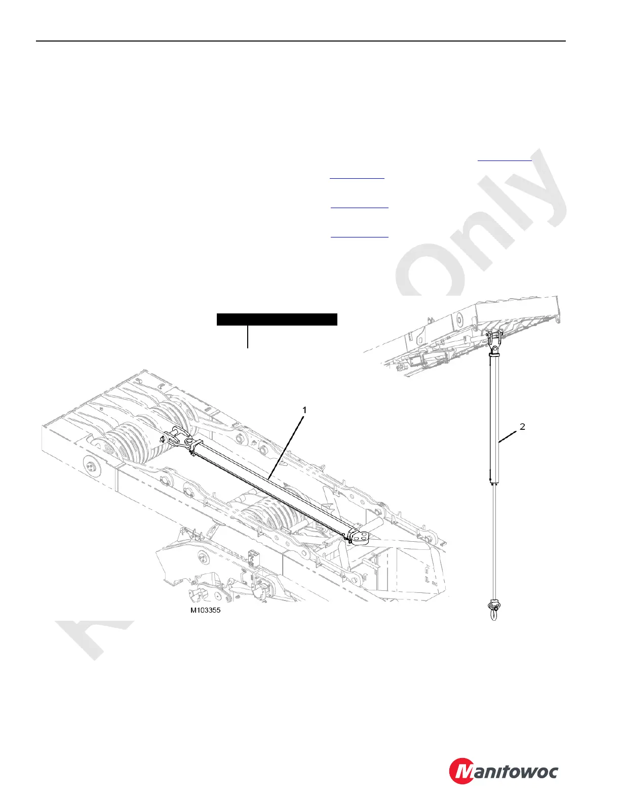
See Figure 10-25
for the stored and working positions of the
self-assembly cylinder.
See Figure 10-26
for the hydraulic schematic of the self-
assembly cylinder circuit.
See Figure 10-28
for the electrical schematic of the self-
assembly cylinder circuit.
Item Description
1 Stored Position
2 Working Position
FIGURE 10-25
Self-Assembly Cylinder Working and Stored Positions