ACCESSORIES MLC650 SERVICE/MAINTENANCE MANUAL
10-50
Published 09-09-16, Control # 229-09
VPC Counterweight Tray Roller Backlash
Adjustment
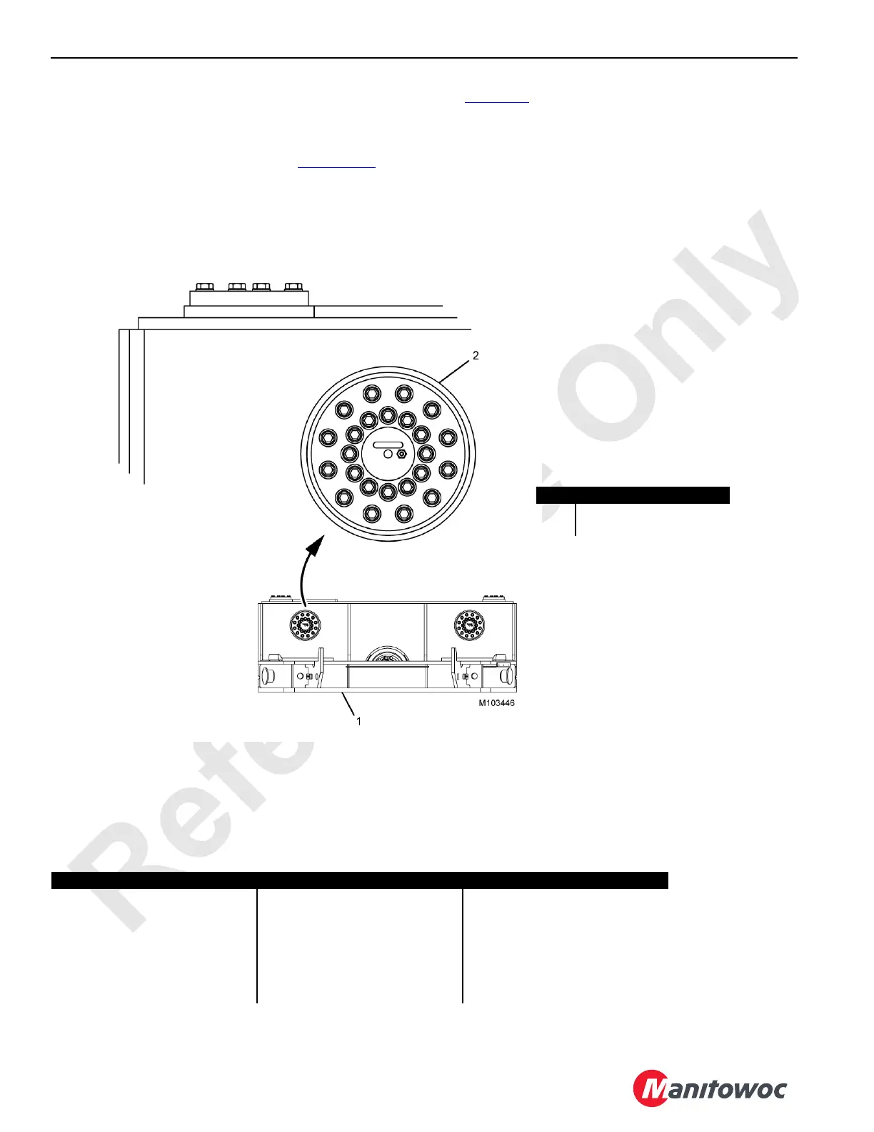
Initially position the roller assembly so that the slot is
horizontal and above the roller axis (see Figure 10-39
). The
shaft of the roller assembly has 2 mm (0.08 in) of
eccentricity. It is possible to adjust the rack and pinion
backlash by rotating the shaft in the bore.
See Table 10-1
for the permissible front and rear adjustment
combinations and resulting change in backlash.
• To decrease backlash, rotate the shaft counter-
clockwise.
• To increase backlash, rotate the shaft clockwise and a
corresponding increase in backlash will result.
• Adjust equally side to side.
Table 10-1. Shaft Angle / Decrease in Backlash
Item Description
1 VPC Counterweight Tray
2 Roller Assembly
FIGURE 10-39
Front Shaft Rotation Angle CCW Rear Shaft Rotation Angle CCW Resulting Decrease in Backlash
0° 0° 0 Initial Position
0° 30° 0,42 mm (0.02 in)
30° 30° 0,85 mm (0.03 in)
30° 60° 1,15 mm (0.05 in)
60° 60° 1,46 mm (0.057 in)
60° 90° 1,58 mm (0.06 in)
90° 90° 1,69 mm (0.07 in)