Manitowoc Published 09-09-16, Control # 229-09 10-29
MLC650 SERVICE/MAINTENANCE MANUAL ACCESSORIES
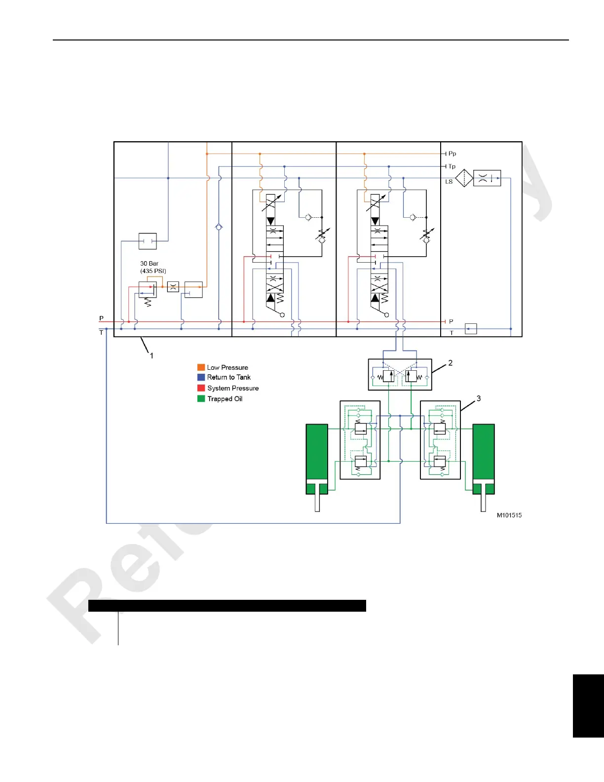
Mast Assist Cylinders Hydraulic Schematic
The hydraulic schematic is shown in the neutral state.
Item Description
1 Mast Assist and Self-Assembly Valve Assembly
2 Load-Hold Counterbalance Valve (set at 275 bar [4000 psi])
3 Cylinder Counterbalance Valve (set at 248 bar [3600 psi]) (qty 4)
FIGURE 10-22