ACCESSORIES MLC650 SERVICE/MAINTENANCE MANUAL
10-8
Published 09-09-16, Control # 229-09
ROTATING BED JACK CYLINDERS
General
This part of Section 10 provides operational information and
electrical and hydraulic schematics for the rotating bed jack
cylinders when in the working position.
Additional component information for this system can be
found in the following sections of the Service Manual:
• Section 2: Hydraulics
• Section 3: Electrical
The rotating bed jack cylinders are controlled by the
following methods:
• Setup remote control
• Manual control levers on the upperworks jacking and
rigging winch valve assembly (see Figure 10-8
)
NOTE: The rotating bed jacks deployment is covered in
Section 4: Deploy Rotating Bed Jacking Cylinders
of the Operator Manual.
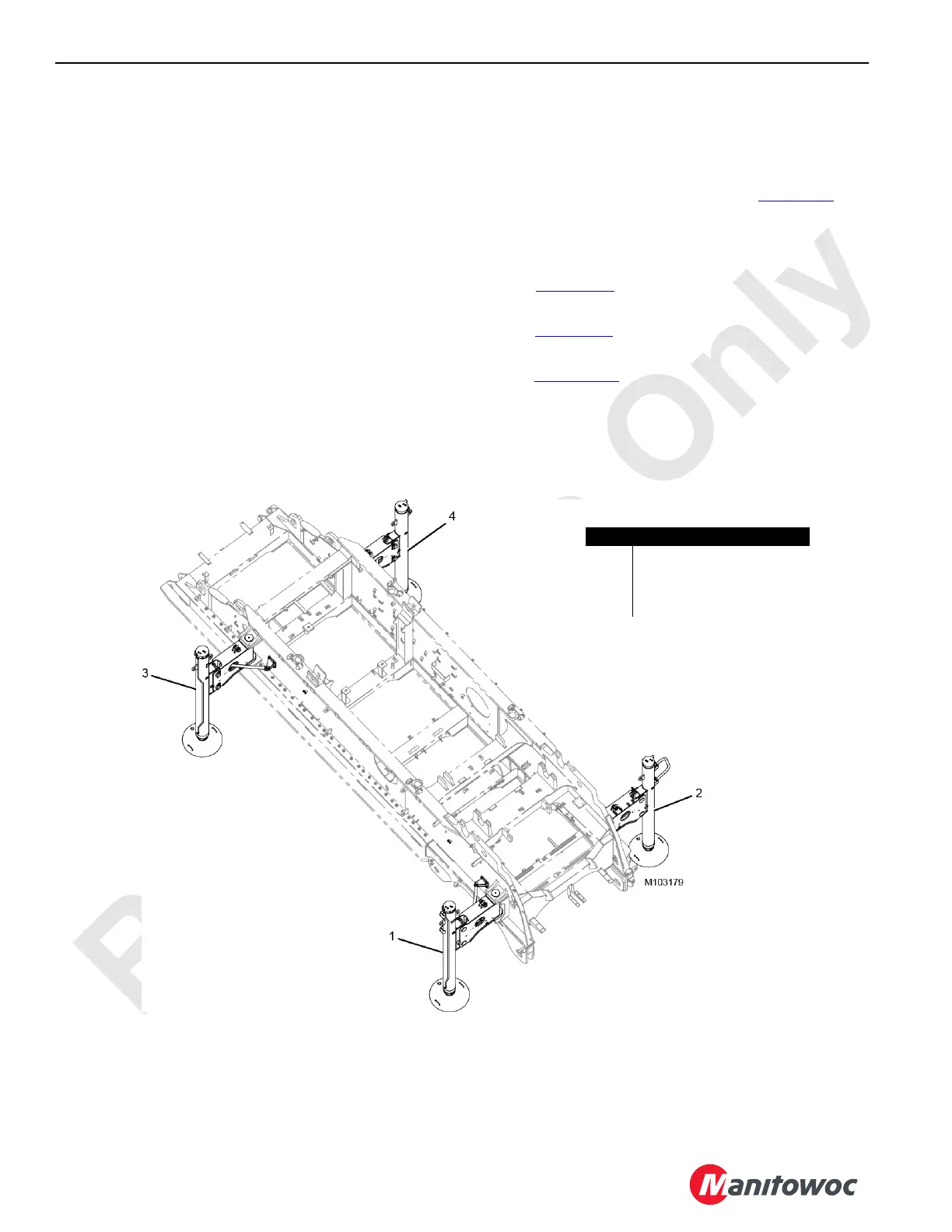
See Figure 10-7
for an illustration of the rotating bed jack
cylinders in the working position.
See Figure 10-9
for the hydraulic schematic of the rotating
bed jack cylinders circuit.
See Figure 10-12
for the electrical schematic of the rotating
bed jack circuit.
Item Description
1 Right Front Jack Cylinder
2 Left Front Jack Cylinder
3 Right Rear Jack Cylinder
4 Left Rear Jack Cylinder
FIGURE 10-7