Manitowoc Published 09-09-16, Control # 229-09 2-3
MLC650 SERVICE/MAINTENANCE MANUAL HYDRAULIC SYSTEM
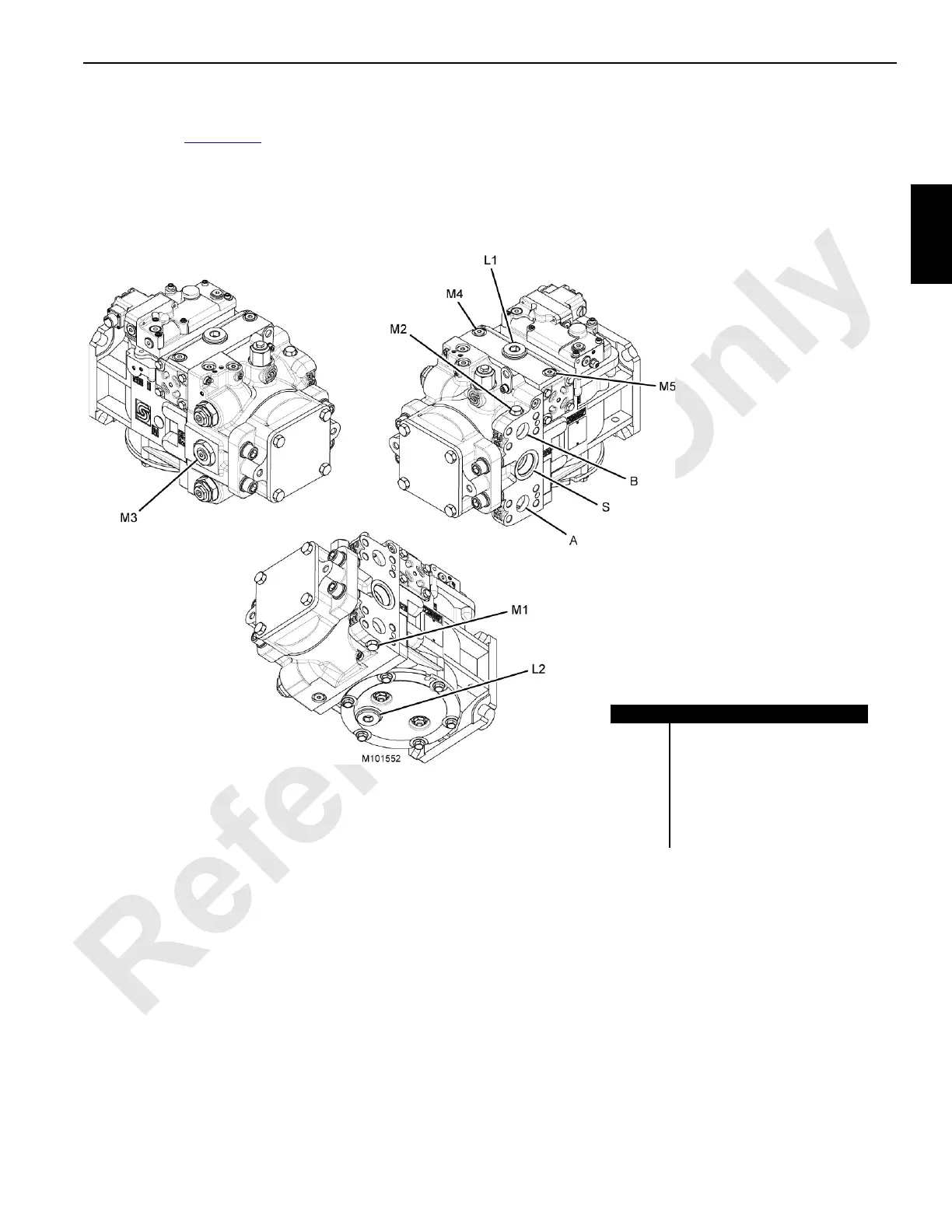
Pump 3
Pump three (Figure 2-3) is a bidirectional variable-
displacement pump providing flow to either drum one or the
left travel motors. A diverter valve, driven by CCM—10,
provides pump flow to either drum one or the left travel
motors, as commanded by the control system. Pump
direction and displacement is controlled by an electronic
displacement control (EDC), driven by the IOLC32 control
module.
FIGURE 2-3
Item Description
A, B Main Pressure Lines
L1, L2 Case Drain Ports
M1 Gauge Port—A
M2 Gauge Port—B
M3 Gauge Port—Charge Pressure
M4, M5 Gauge Ports—Servo Pressure
S Suction Line—Charge Pump