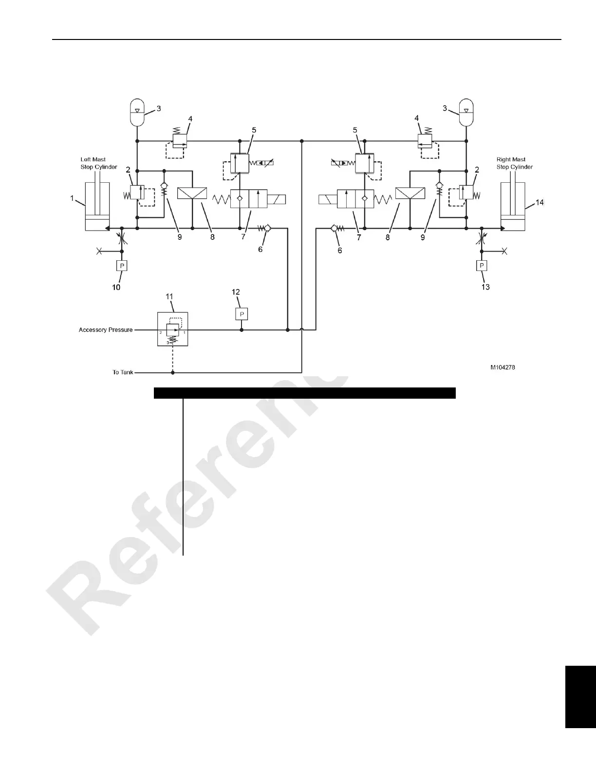
FIGURE 10-60
Item Description
1 Left Mast Stop Cylinder
2 Relief Valve (set at 221 bar [3200 psi]) (qty 2)
3 Integrated Cylinder Accumulator (qty 2)
4 Relief Valve (set at 16,6 bar [240 psi]) (qty 2)
5 Mast Cylinder Pressure-Reducing Solenoid Valve (qty 2)
6 Check Valve (qty 2)
7 Mast Cylinder Directional Control Solenoid Valve (qty 2)
8 Rupture Disc (qty 2)
9 Bypass Check Valve (qty 2)
10 Left Mast Cylinder Pressure Transducer
11 Mast Cylinder System Pressure-Reducing Valve (set at 31 bar [450 psi])
12 Mast Cylinder System Pressure Transducer
13 Rignt Mast Cylinder Pressure Transducer
14 Right Mast Stop Cylinder