Manitowoc Published 09-09-16, Control # 229-09 10-41
MLC650 SERVICE/MAINTENANCE MANUAL ACCESSORIES
VPC AND VPC-MAX SYSTEMS
General
This part of Section 10 provides the electrical and hydraulic
control of the VPC and VPC-MAX counterweight system.
The systems that are covered are as follows:
• VPC Counterweight Tray (see Figure 10-33
)
• VPC-MAX Trolley (see Figure 10-41
)
• VPC-MAX Beam (see Figure 10-41
)
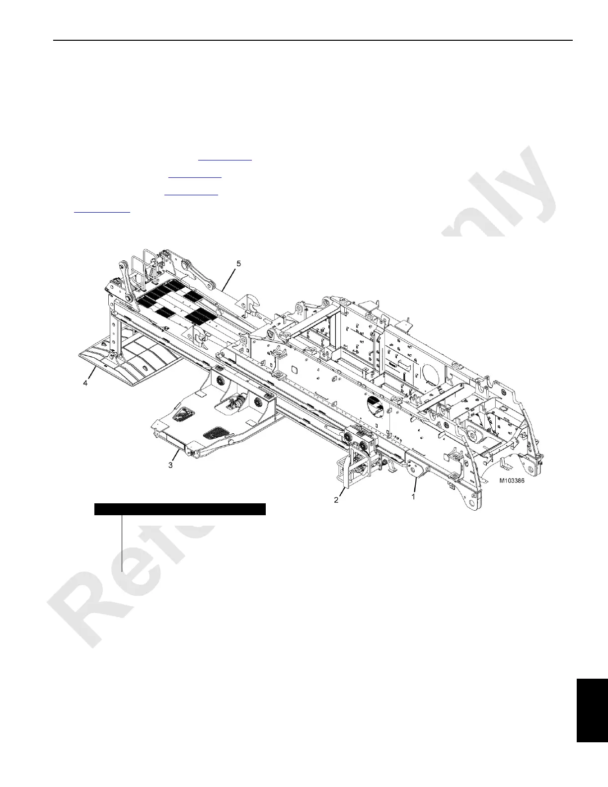
See Figure 10-32
for an illustration of the VPC and VPC-
MAX counterweight system.
Information and adjustment procedures are provided for the
following:
• Speed sensors
• Absolute encoders
• Limit switches
• Roller backlash
Additional component information for this system can be
found in the following sections of the Service Manual:
• Section 2: Hydraulics
• Section 3: Electrical
Item Description
1 Rotating Bed
2 VPC-MAX Trolley
3 VPC Counterweight Tray
4 Frame Assembly Auxiliary Member
5 VPC-MAX Beam
FIGURE 10-32