Manitowoc Published 09-09-16, Control # 229-09 10-1
MLC650 SERVICE/MAINTENANCE MANUAL ACCESSORIES
SECTION 10
ACCESSORIES
ADAPTER FRAME-TO-ROTATING BED PIN
PULLERS
General
This part of Section 10 provides operational information and
electrical and hydraulic schematics for the following
systems:
• Adapter frame-to-rotating bed front pin pullers
• Adapter frame-to-rotating bed rear pin pullers
Additional component information for these systems can be
found in the following sections of the Service Manual:
• Section 2: Hydraulics
• Section 3: Electrical
Adapter Frame-to-Rotating Bed Front Pin
Pullers Operation
The adapter frame-to-rotating bed front pin pullers are
controlled by the setup remote.
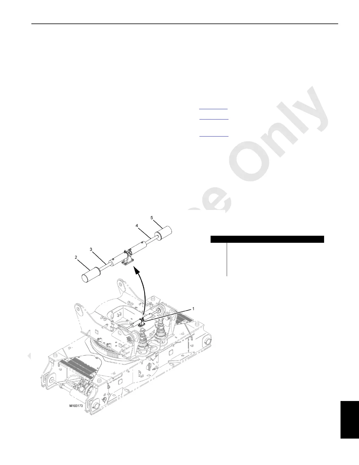
See Figure 10-1
for an illustration of the front pin pullers.
See Figure 10-2
for the hydraulic schematic of the front pin
pullers circuit.
See Figure 10-3
for the electrical schematic of the front pin
pullers circuit.
Setup Remote Overview
NOTE: The setup remote is covered in Section 4 of the
Operator Manual.
The setup remote control communicates with the CCM-10
control module using the controller area network bus (CAN
Bus). The crane control modules use the CAN Bus to
communicate with each other.
.
Item Description
1 Adapter Frame Front Pin Puller Assembly
2Pin
3 Cylinder Front Pin Puller Female
4 Cylinder Front Pin Puller Male
5Pin
FIGURE 10-1