Manitowoc Published 09-09-16, Control # 229-09 4-1
MLC650 SERVICE/MAINTENANCE MANUAL BOOM
SECTION 4
BOOM
GENERAL MAINTENANCE
This section contains maintenance and adjustment
instructions for the limit devices used with the boom and
luffing jib attachment.
It also contains maintenance and inspection of the following
components:
• Straps
• Fleeting Sheaves
BOOM AND LUFFING JIB ANGLE
INDICATOR CALIBRATION
An angle sensor (Figure 4-1) is located inside the boom and
luffing jib tops. The sensors are calibrated on the Range
Capacity Limiter/ Range Capacity Indicator (RCL/RCI)
display and do not require adjustment.
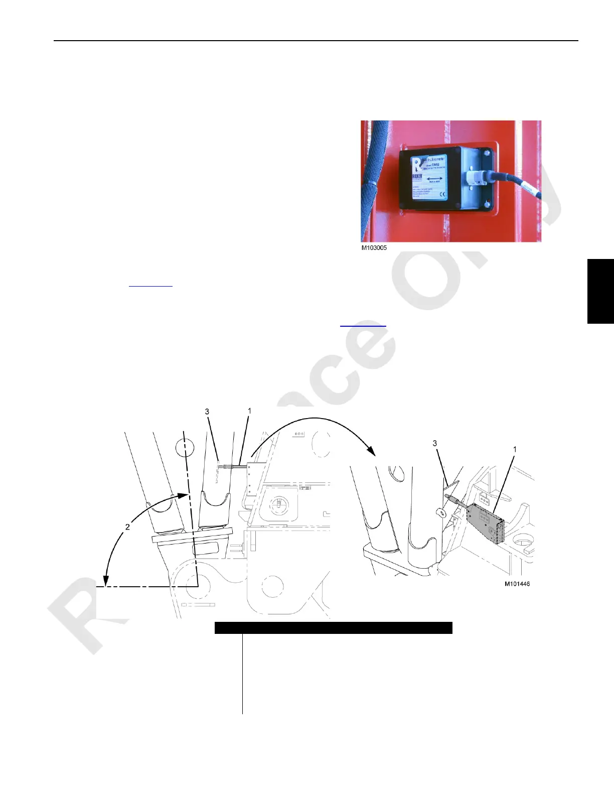
BOOM STOP LIMIT SWITCH
When the boom is at a position other than the maximum
allowable angle, the limit switch in the boom stop switch unit
(1, Figure 4-2
) is closed, providing a continuous 24 V
DC
signal to the ID07 input on the IOLC30 control module.
If the boom reaches the maximum allowable angle for your
boom/jib configuration, the limit switch will open (voltage at
the ID07 input drops to 0 V
DC
), signaling the control system
to stop the boom hoist and apply the hoist brake.
Item Description
1 Boom Stop Switch Unit
2 Maximum Switch Boom Angle:
84.5° Boom only with VPC-MAX
86.4° Boom with Luffing Jib and without VPC-MAX
86.4° Boom with Luffing Jib and VPC-MAX
86.4° Boom only with VPC
3 Boom Stop Plate
FIGURE 4-2