HOISTS MLC650 SERVICE/MAINTENANCE MANUAL
5-68
Published 09-09-16, Control # 229-09
Main Boom Lower Point 1M Boom Cap Block-Up
Limit Switch
Adjustment
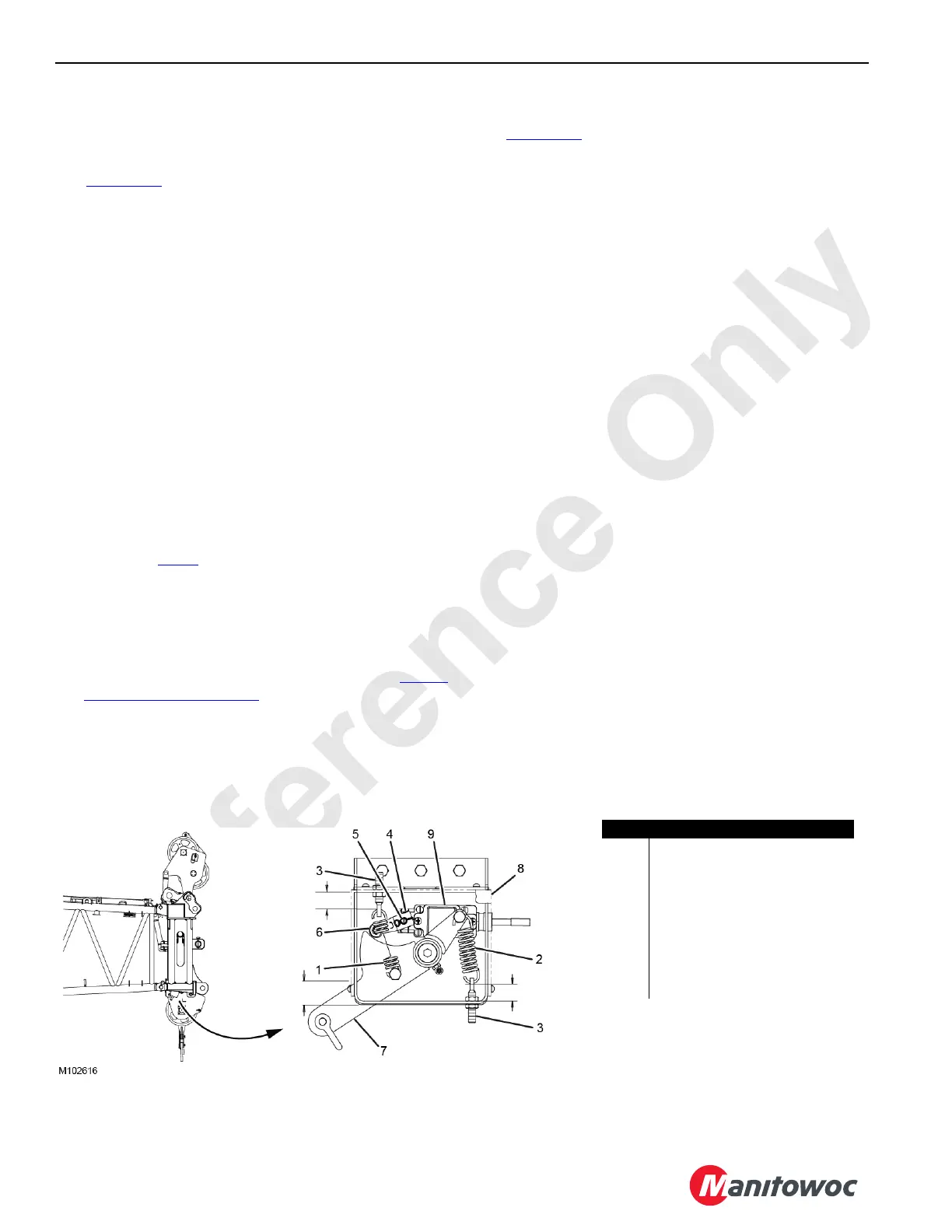
See Figure 5-36 for the following procedure.
Lower the boom onto blocking at the ground level and adjust
each limit switch as follows.
1. Remove the block-up limit assembly cover (8) to access
the internal components.
2. Remove the spring (1).
3. Adjust the spring (2) tension so there is enough force to
lift the weight of the chain and rotate the actuating lever
(7) when the weight is lifted.
4. Manually lift the weight to allow the actuating lever to
rotate upward.
5. Hold the actuating lever at Dimension A from the spring
return position.
6. Loosen the setscrew (4) on the limit switch actuator arm
(6).
7. Using a screwdriver, hold the roller on the limit switch
actuator arm against the actuating lever while
performing step 8
.
8. Turn the limit switch shaft (5) clockwise until the switch
just actuates, then tighten the setscrew on the limit
switch actuator arm.
9. Attach the spring.
10. Test the limit switch for proper operation (see Weekly
Maintenance on page 5-62).
11. Repeat the adjustment steps until the limit switch
operates properly.
12. Install the block-up limit assembly cover when testing is
complete.
Replacement
See Figure 5-36 for the following procedure.
1. Remove the block-up limit assembly cover (8).
2. Remove four mounting screws on the limit switch (9).
3. Remove the limit switch cover to expose the internal
wiring connections.
4. Disconnect the electrical wires inside the limit switch.
5. Remove the cable restraint nut and carefully pull the
electrical cable and wires from the limit switch.
6. Loosen the setscrew (4) and remove the limit switch
actuator arm (6).
7. Insert the electrical cable into the new limit switch and
connect the wiring.
The jumper wires and the receptacle lead wires must be
stripped to 6,35 mm (0.25 in) to properly fit the U-clamp
screw termination.
8. Install and tighten the cable restraint nut to the limit
switch.
9. Install the limit switch cover.
10. Install the limit switch actuator arm.
11. Install the limit switch onto the block-up limit assembly
using four mounting screws.
12. Perform the main boom lower point 1M boom cap block-
up limit adjustment procedure.
13. Adjust the tension of the spring (1) by adjusting the
corresponding eyebolt (3) to Dimension C.
Adjust the tension of the spring (2) by adjusting the
corresponding eyebolt to Dimension B.
14. Install the block-up limit assembly cover.
Item Description
1Spring
2Spring
3 Eyebolt
4Setscrew
5 Limit Switch Shaft
6 Limit Switch Actuator Arm
7 Actuating Lever
8 Block-Up Limit Assembly Cover
9 Limit Switch
FIGURE 5-36
Dim. A = 26,4 mm
Dim. B
= 22,6 mm
Dim. C = 24,6 mm