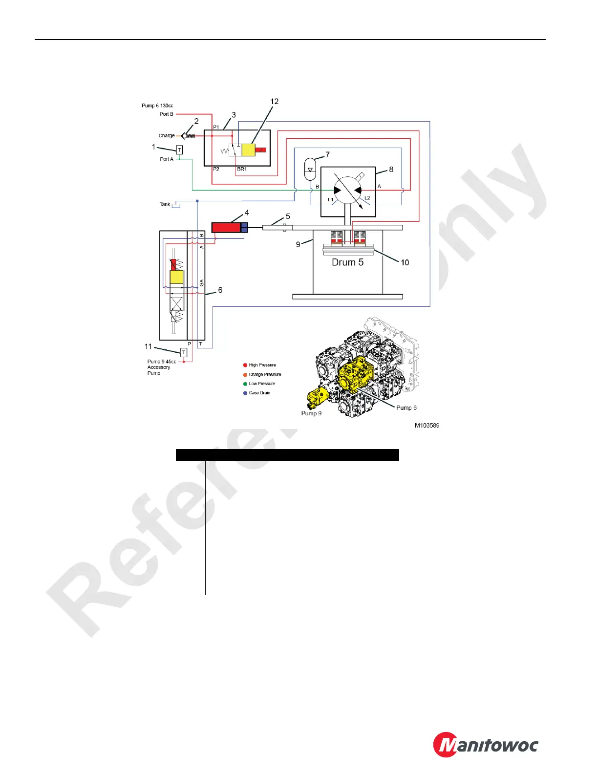
EasyManua.ls Logo

Manitowoc MLC650 - Drum 5 Lowering Hydraulic Schematic

Manitowoc MLC650
376 pages
To Next Page IconTo Next Page
To Previous Page IconTo Previous Page
Loading...
Reference Only
HOISTS MLC650 SERVICE/MAINTENANCE MANUAL
5-38
Published 09-09-16, Control # 229-09
Drum 5 Lowering Hydraulic Schematic
FIGURE 5-19
Item Description
1 Pump 6 Pressure Transducer (drum 5 psi)
2 Charge Pressure Check Valve (0,35 bar [5 psi])
3 Charge and Brake Manifold Assembly
4 Drum Pawl Actuator
5 Drum Pawl Assembly
6 Pawl Control Manifold
7 Accumulator
8 Hydraulic Motor (variable 160 cc)
9 Drum Hoist Gearbox and Brake Assembly
10 Drum Brake Pressurized (disengaged)
11 Pump 9 Pressure Transducer (acc systems psi)
12 Drum Brake Release Solenoid Valve

Table of Contents

Other manuals for Manitowoc MLC650

Related product manuals