ACCESSORIES MLC650 SERVICE/MAINTENANCE MANUAL
10-72
Published 09-09-16, Control # 229-09
Loss of Load Operation
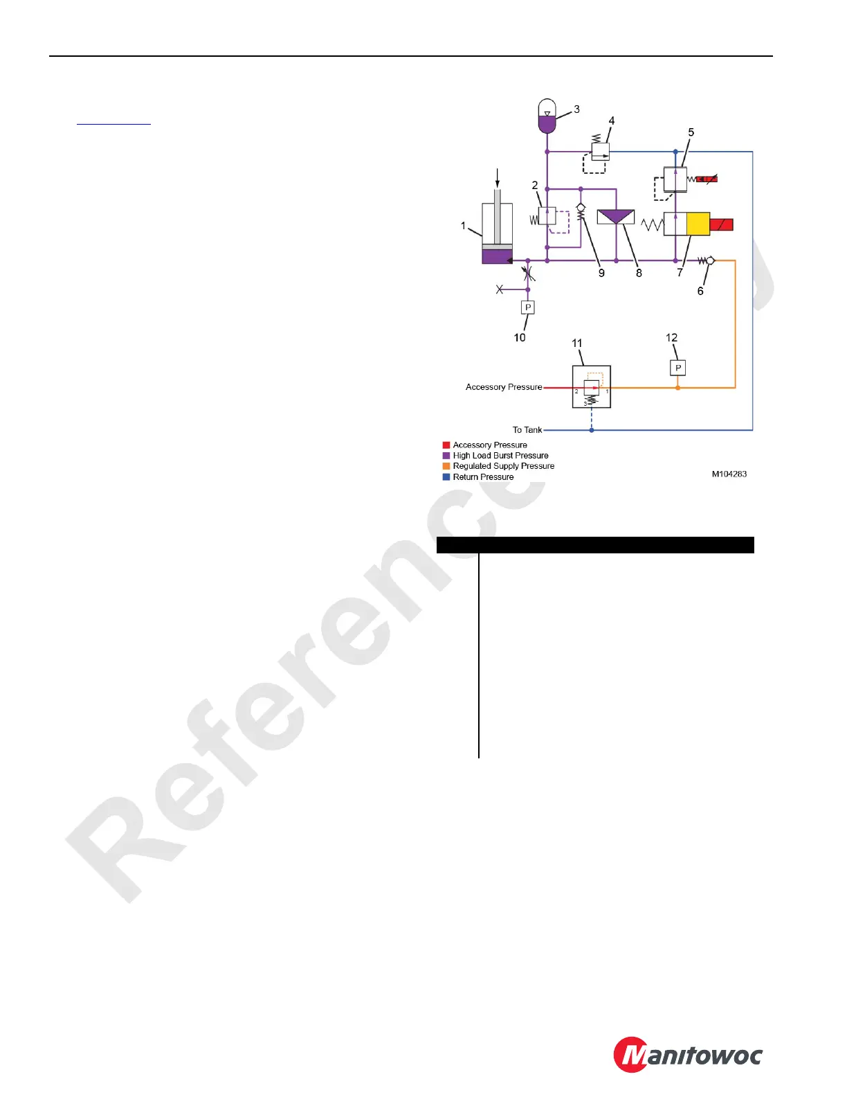
See Figure 10-59 for the following.
During normal cylinder retraction, the mast cylinder
pressure-reducing solenoid valve (5) regulates the cylinder
bore pressure. But during a load loss situation, the mast stop
cylinders rapidly compress, causing a pressure spike. When
the maximum hydraulic flow through the reducing valve is
reached, the reducing valve will act as an orifice, causing the
cylinder bore pressure to increase beyond the reducing
valve setting.
When the pressure in the cylinder bore reaches 221 bar
(3200 psi), the relief valve (2) opens, sending hydraulic fluid
to the integrated cylinder accumulator (3), charging the
accumulator.
If the cylinder bore pressure reaches 310 bar (4500 psi), the
pressure differential across the relief valve will cause the
rupture disc (8) to burst, allowing an additional flow path from
the cylinder bore to the accumulator.
NOTE: Whenever a rupture disc bursts, it must be
replaced and the whole cylinder fully inspected,
including the seals and rod, prior to the cylinder
being put back into service.
FIGURE 10-59
Loss of Load
(rupture disc shown burst)
Item Description
1 Mast Stop Cylinder
2 Relief Valve (set at 221 bar [3200 psi])
3 Integrated Cylinder Accumulator
4 Relief Valve (set at 16,6 bar [240 psi])
5 Mast Cylinder Pressure-Reducing Solenoid Valve
6 Check Valve
7 Mast Cylinder Directional Control Solenoid Valve
8Rupture Disc
9 Bypass Check Valve
10 Mast Cylinder Pressure Transducer
11 Mast Cylinder System Pressure-Reducing Valve
(set at 31 bar [450 psi])
12 Mast Cylinder System Pressure Transducer