Manitowoc Published 09-09-16, Control # 229-09 10-69
MLC650 SERVICE/MAINTENANCE MANUAL ACCESSORIES
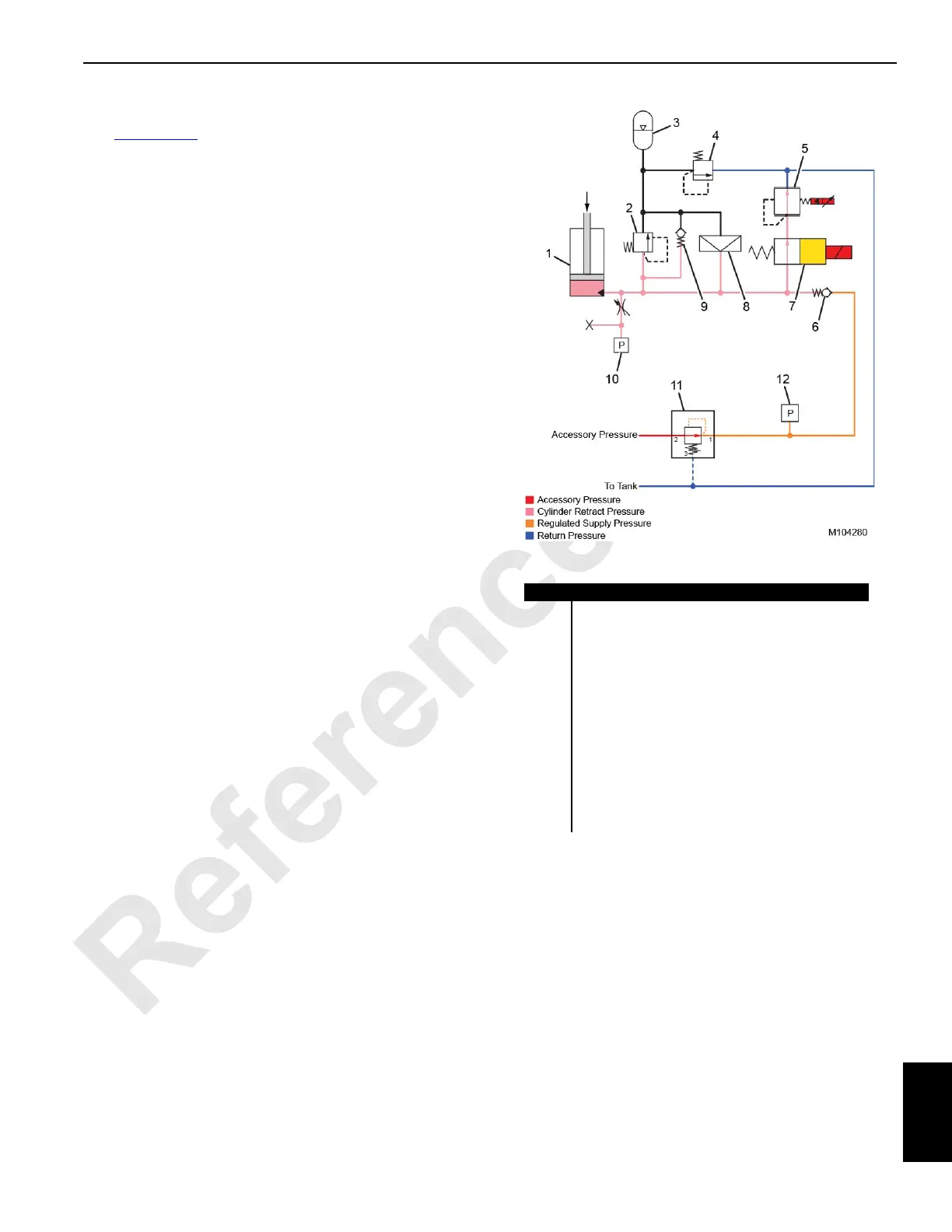
Normal Operation—Cylinder Retraction
See Figure 10-56 for the following.
When the load on the mast stop cylinder increases during
cylinder retraction, the pressure on the bore side of the
cylinder increases. The mast cylinder pressure transducer
(10), located on each cylinder, detects this pressure and
provides a feedback signal to the IOLC30 control module.
At this point, the cylinder pressure is higher than the system
regulated supply pressure. This causes the check valve (6)
to close, preventing hydraulic fluid from flowing back into the
system supply circuit. The IOLC33 control module then
sends a 24 VDC output voltage to the mast cylinder
directional control solenoid valve (7), energizing the
solenoid. The solenoid valve shifts position, allowing
hydraulic fluid to flow to the mast cylinder pressure-reducing
solenoid valve (5). At the same time, the IOLC30 control
module sends a pulse width modulation (PWM) signal to this
solenoid, modulating the solenoid valve to allow the high
pressure oil to flow back to the hydraulic tank. This reduces
the pressure in the cylinder bore until the target pressure is
obtained.
NOTE: When the mast cylinder pressure-reducing
solenoid valve is de-energized, the valve acts as a
relief valve when the pressure becomes equal to or
more than 241 bar (3500 psi). The relief setting
provided by this valve is higher than the maximum
operating pressure provided by the relief valve (2).
Item Description
1 Mast Stop Cylinder
2 Relief Valve (set at 221 bar [3200 psi])
3 Integrated Cylinder Accumulator
4 Relief Valve (set at 16,6 bar [240 psi])
5 Mast Cylinder Pressure-Reducing Solenoid Valve
6 Check Valve
7 Mast Cylinder Directional Control Solenoid Valve
8Rupture Disc
9 Bypass Check Valve
10 Mast Cylinder Pressure Transducer
11 Mast Cylinder System Pressure-Reducing Valve
(set at 31 bar [450 psi])
12 Mast Cylinder System Pressure Transducer
FIGURE 10-56
Cylinder Retraction