ACCESSORIES MLC650 SERVICE/MAINTENANCE MANUAL
10-52
Published 09-09-16, Control # 229-09
VPC-MAX Trolley Operation
The VPC-MAX trolley is attached to the VPC-MAX beam by
two hydraulically actuated pins controlled by the setup
remote. When pinned they move as one unit.
The VPC-MAX trolley movement is controlled by the
following methods:
• On-board computer control
• Setup remote
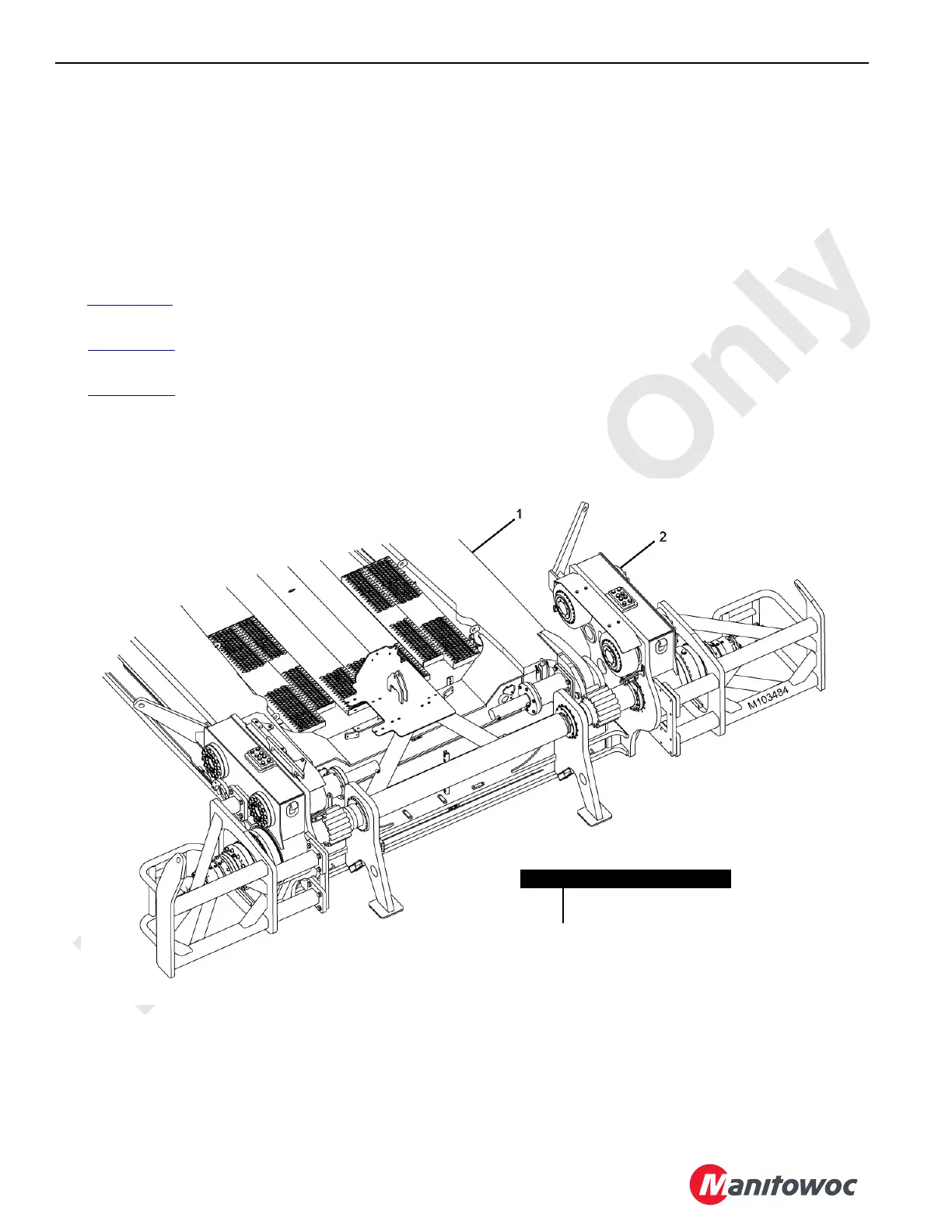
See Figure 10-41
for an illustration of the VPC-MAX trolley
and beam.
See Figure 10-42
for the hydraulic schematic of the VPC-
MAX trolley motor circuit.
See Figure 10-43
for the electrical schematic of the VPC-
MAX trolley motor circuit.
Setup Remote Overview
NOTE: The setup remote is covered in Section 4 of the
Operator Manual.
The setup remote control communicates with the CCM-10
control module using the controller area network bus (CAN
Bus). The crane control modules use the CAN Bus to
communicate with each other.
Item Description
1 VPC-MAX Beam
2 VPC-MAX Trolley
FIGURE 10-41