ELECTRICAL SYSTEM MLC650 SERVICE/MAINTENANCE MANUAL
3-4
Published 09-09-16, Control # 229-09
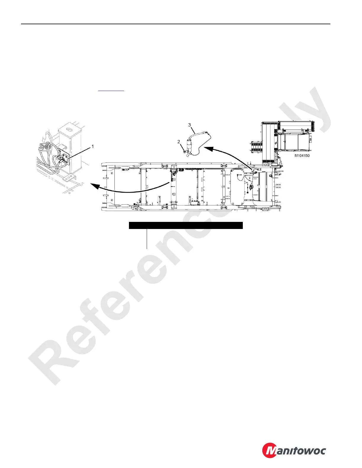
Rotating Bed Ground Points
There are two major ground points on the rotating bed:
• Rotating bed ground point (1)
• Live mast-to-rotating bed ground point (2)
The rotating bed ground point (1) is a ground stud located at
the left engine mount bracket (Figure 3-2
). The ground stud
provides a single connection point for the ground circuit of all
the electrical devices located on the rotating bed and the
carbody. A ground cable connects the battery negative (-)
terminal to the ground stud.
The live mast-to-rotating bed ground point (2) provides a
path to ground for electrical components on the live mast
frame. It electrically connects the left arm of the live mast to
the rotating bed frame.
The ground cable cap assembly (3) provides connector
protection when the live mast is not attached to the rotating
bed.
FIGURE 3-2
Item Description
1 Rotating Bed Ground Point
2 Live Mast-to-Rotating Bed Ground Point
3 Ground Cable Cap Assembly