Manitowoc Published 09-09-16, Control # 229-09 3-17
MLC650 SERVICE/MAINTENANCE MANUAL ELECTRICAL SYSTEM
Control Module Devices
The control modules communicate with output devices to
control crane movement and with input devices to read crane
status. The following sections detail the operation of these
devices.
Pressure Transducers
A controller provides power to the pressure transducer. The
pressure transducers send an analog input signal to the
controller that is proportional to the hydraulic pressure at the
transducer connection. The controllers monitor hydraulic
pressures to use as feedback in control algorithms and to
provide status information to the operator. Pressure
transducers are used to monitor the following:
• Drum system pressures
• Swing system pressure
• Accessory system pressure
• Track pressure
• Variable position counterweight (VPC)
actuator pressure
• Cooler fan pressure
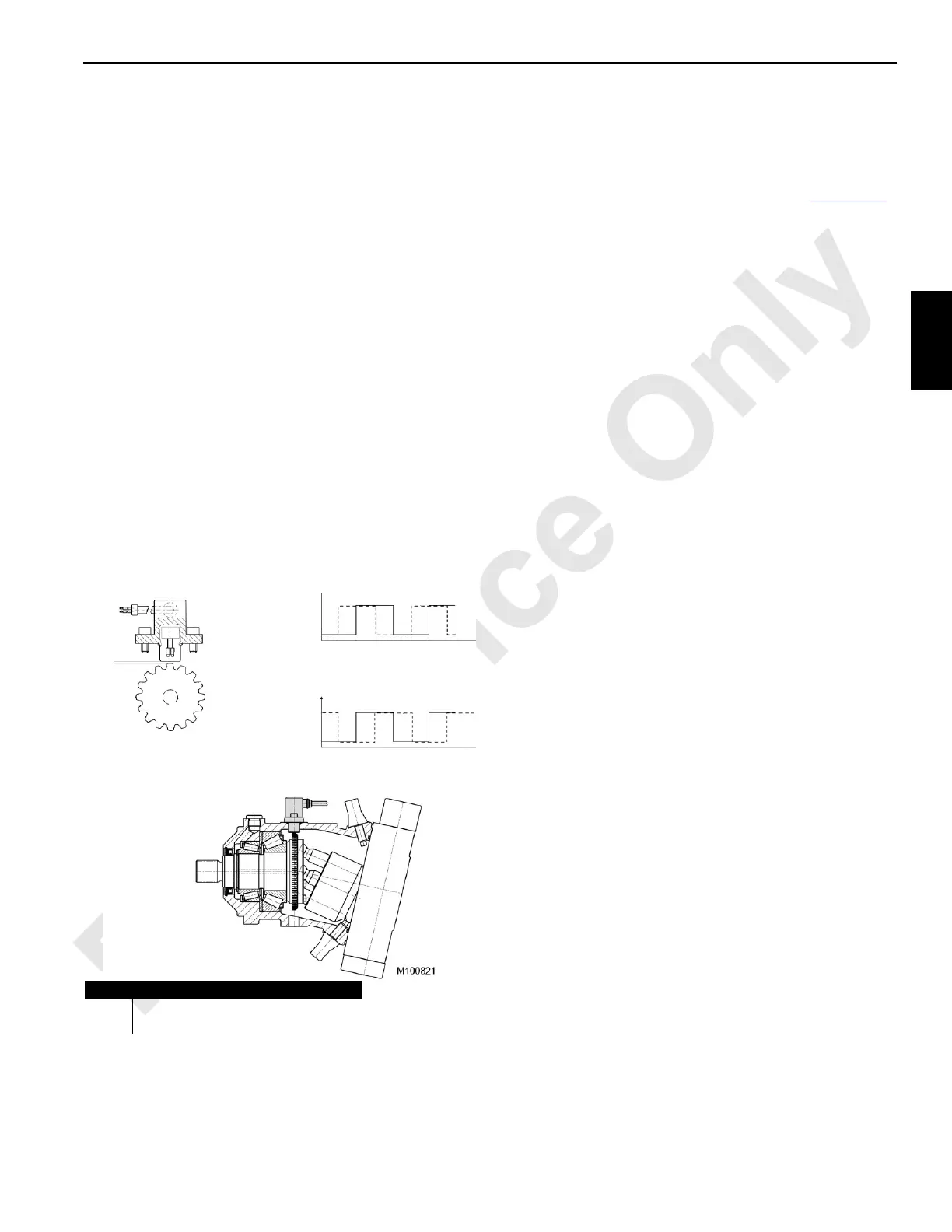
Motor Speed Sensors
A controller provides power to Hall-effect speed sensors
located within the hydraulic motors that drive the drums
rotating bed, VPC, and crawlers. A gear wheel within the
motor has teeth that move past the speed sensor as a motor
shaft spins, causing the sensor to produce two square-wave
signals that are offset with a 90° phase delay (Figure 3-10
).
These signals are read at the frequency inputs of the
controller.
The frequency of the square waves is determined by the
number of teeth on the circumference of the gear wheel and
shaft speed. The rotational direction is determined by which
signals phase leads the other. Software uses the square-
wave frequency and phase information to calculate the
rotational speed and direction of the motor.
Limit Switches—Dual Contact
In the non-tripped state, a controller provides power to the
normally closed contact and grounds the normally open
contact. A controller digital input reads the applied power
through the normally closed contact back through the
common center terminal as a logic high. When the switch is
tripped, the normally closed contact opens, breaking the
current path through the common terminal. At the same time,
the normally open contact closes, grounding the common
terminal and sending a controller digital input a logic low
signal.
Dual contact limit switches are used to sense the travel limits
of the following crane functions:
• Drums 1, 2, 3, 5, and 6 minimum bail limit
• Drums 4, 5, and 6 pawl limit
• Maximum boom angle limit
• Mast position limit
• VPC beam in and out maximums
• VPC tray in and out maximums
• VPC-MAX™ beam in and out maximums
• VPC-MAX tray in and out maximums
• VPC-MAX beam up left and right
• VPC-MAX beam on hook left and right
• Gantry limit
Limit Switches—Single Contact
In the non-tripped state, a controller provides power to the
normally closed contact. A controller digital input reads the
applied power back through the normally closed contact as a
logic high. When the switch is tripped, the normally closed
contact opens, breaking the current path through the
common terminal. The controller digital input reads this as a
logic low.
FIGURE 3-10
Item Description
A Clockwise Rotation Signals
B Counterclockwise Rotation Signals
A
B