CHARGING & STARTING SYSTEM
90-857046R1 NOVEMBER 2001 Page 2B-13
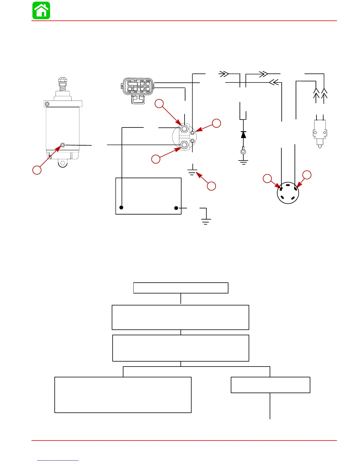
Starting Circuit Troubleshooting Flow Chart
The following “STARTING CIRCUIT TROUBLESHOOTING FLOW CHART” is designed as
an aid to troubleshooting the starting circuit. This flow chart will accurately locate any exist-
ing malfunction. Location of “TEST POINTS” (called out in the chart) are numbered in dia-
gram below.
Starter Motor Does Not Turn
SAFETY WARNING: Disconnect BLACK (with Yellow
Sleeve) (starter motor) cable from starter solenoid test
point 1 BEFORE making tests 1-thru-7 to prevent unex-
pected engine cranking.
TEST 1
Use an ohmmeter (R x 1 scale) and connect meter leads be-
tween NEGATIVE (-) battery post and common powerhead
ground.
No continuity indicated; there is an open circuit in the BLACK
NEGATIVE (-) battery cable between the NEGATIVE (-) battery
post and the powerhead.
• Check cable for loose or corroded connections.
• Check cable for open circuit.
Continuity Indicated
Proceed to TEST 2, on next page.
Starting Circuit Troubleshooting Flow Chart
+
NEUTRAL
START
SWITCH
IGNITION SWITCH
STARTER
STARTER
SOLENOID
BATTERY
FUSE HOLDER ASSEMBLY
–
BLK = Black
BLU = Blue
BRN = Brown
GRY = Gray
GRN = Green
ORN = Orange
PNK = Pink
PUR = Purple
RED = Red
TAN = Tan
WHT = White
YEL = Yellow
RED/PUR
RED
YEL/RED
BLK
BLK
1
2
3
4
5
6
BLK
(with
YEL SLEEVES)
BLK
(with
RED SLEEVES)
BLK
BLK
BRN
YEL/RED
7
RED/PUR
YEL/RED
BRN
DIODE
15

 Loading...