WIRING DIAGRAMS
Page 2D-14 90-857046R1 NOVEMBER 2001
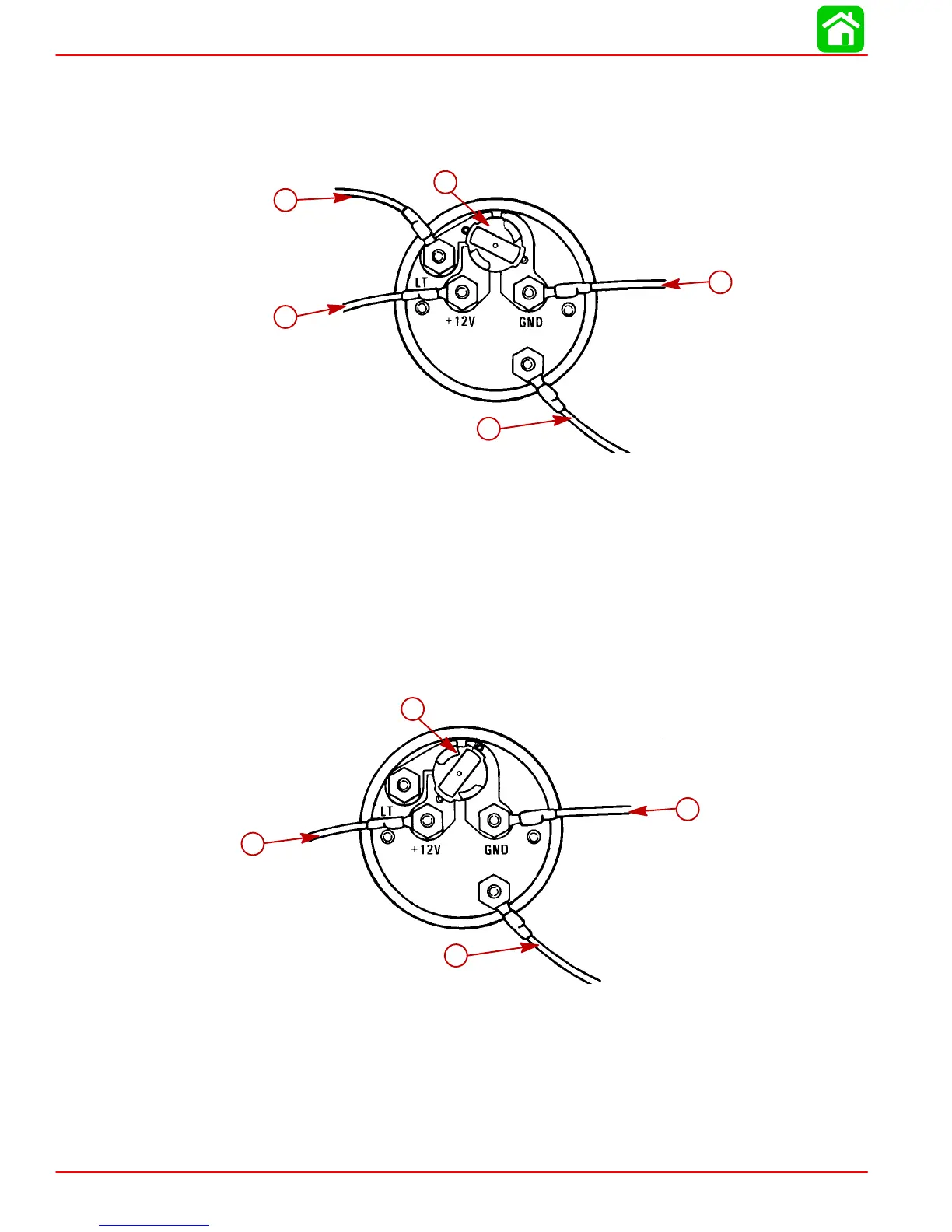
Water Temperature Gauge
WIRING DIAGRAM A
Use this wiring diagram when using a separate light switch for instrument lighting.
SEND
c
b
e
d
a
a-PURPLE - Connect to Positive (+) 12 Volt
b-Light Switch Wire - 12 Volt
c-Position Light Bulb to the Switched Position
d-BLACK - Connect to Negative (-) Ground
e-TAN - Connect to TAN lead located at the tachometer receptacle on Com-
mander Side Mount Remote Control or TAN lead coming from Accessary Igni-
tion/Choke Assembly.
WIRING DIAGRAM B
Use this wiring diagram when instrument lighting is wired directly to the ignition key switch.
(Instrument lights are on when ignition key is turned on).
51105
SEND
b
d
c
a
a-PURPLE - Connect to Positive (+) 12 Volt
b-Position Light Bulb to the Unswitched Position
c-BLACK - Connect to Negative (-) Ground
d-TAN - Connect to TAN lead located at the tachometer receptacle on Com-
mander Side Mount Remote Control or TAN lead coming from Accessary Igni-
tion/Choke Assembly.