WIRING DIAGRAMS
90-857046R1 NOVEMBER 2001 Page 2D-15
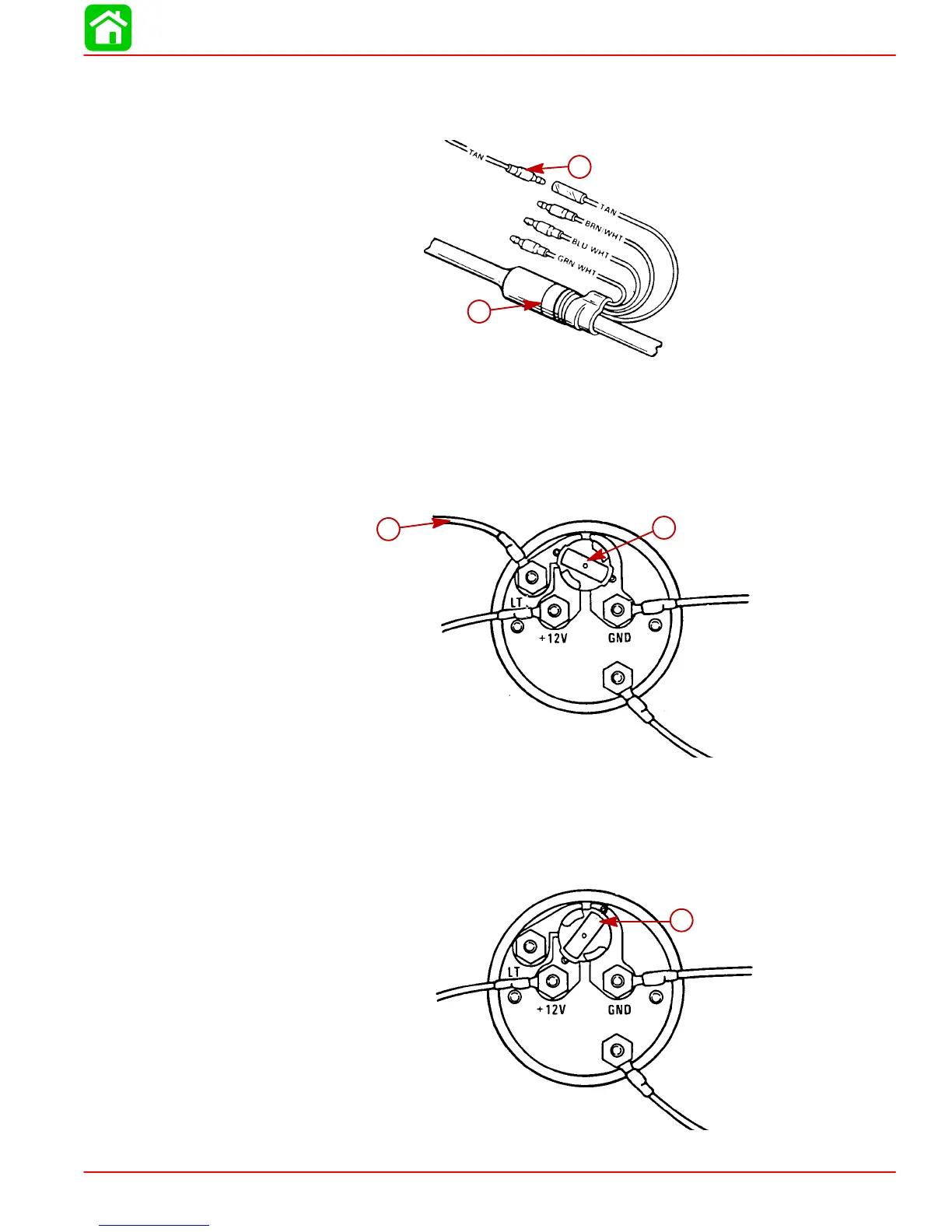
Route TAN lead on starboard side of engine to engine/remote control harness. Connect as
shown.
IMPORTANT: Tape back and isolate any unused wiring harness leads.
28086
a
b
a-Lead from Temperature Sender
b-Engine/Remote Control Harness
Engine Synchronizer Wiring Diagram
LIGHT BULB POSITION A
Use this position when using a separate light switch for instrument lighting.
SEND
51105
a
b
a-Light Switch Wire - 12 Volt
b-Position Light Bulb to the Unswitched Position
LIGHT BULB POSITION B
Use this position when instrument lighting is wired directly to the ignition key switch. (Instru-
ment lights are on when ignition key switch is turned on).
SEND
51106
a
a-Position Light Bulb to the Switched Position