WIRING DIAGRAMS
Page 2D-10 90-857046R1 NOVEMBER 2001
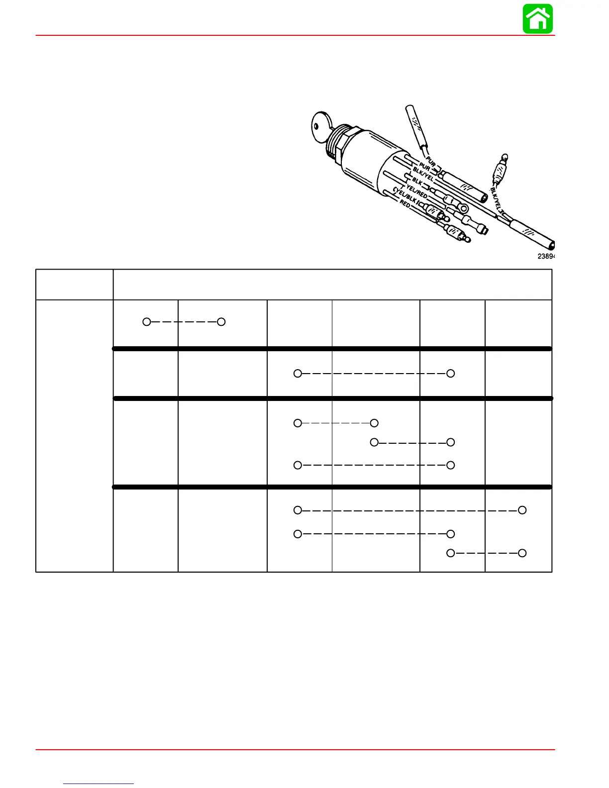
Commander 2000 Key Switch Test
1. Disconnect remote control wiring harness and instrument panel connector.
2. Set ohmmeter on R x 1 scale for the following tests:
KEY
POSITION
OFF
RUN
START
CHOKE*
CONTINUITY SHOULD BE INDICATED AT THE FOLLOWING POINTS:
BLK BLK/YEL RED YEL/RED PUR YEL/BLK
BLK = Black
PUR = Purple
RED = Red
YEL = Yellow
*Key switch must be positioned to “RUN” or “START” and key pushed in to actuate
choke for this test.
NOTE: If meter readings are other than specified in the preceding tests, verify that switch
and not wiring is faulty. If wiring checks ok, replace switch.