CYLINDER HEAD
90-857046R1 NOVEMBER 2001 Page 4A-19
Adjusting Valves
1. Perform the following adjustment steps:
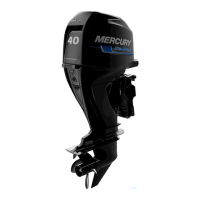
a. Turn the driven gear and align the “1 / ∆” mark on the driven gear with the “∆” mark
on the cylinder block.
b. Adjust the intake and exhaust valve clearance for cylinder #1.
c. Turn the driven gear 120° clockwise and align the “∆” mark on the driven gear with
the “∆” on the cylinder block.
d. Adjust the intake and exhaust valve clearance for cylinder #2
e. Turn the driven gear 120° clockwise and align the “∆” mark on the driven gear with
the “∆” on the cylinder block.
f. Adjust the intake and exhaust valve clearance for cylinder #3
a
c
57191
b
d
1
a-Cylinder Block “∆” Mark
b-Driven Gear “1 or ∆” Mark (Cylinder #1)
c-Driven Gear “∆” Mark at 120° (Cylinder #2)
d-Driven Gear “∆” Mark at 240° (Cylinder #3)
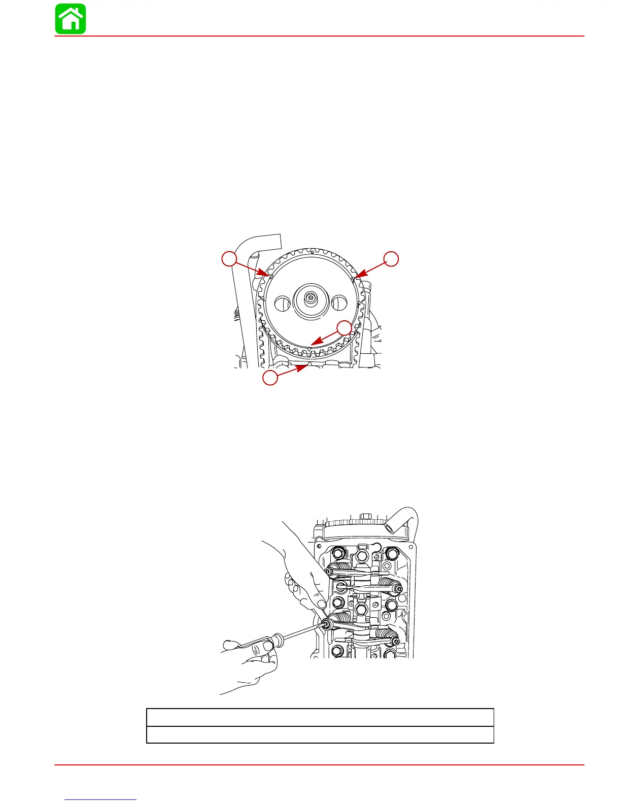
2. Tighten the lock nuts.
NOTE: When tightening lock nuts, hold the adjusting screw with a screw driver to prevent
it from moving.
Valve Adjusting Lock Nut Torque
120 lb. in. (13.5 N·m)