Home
Mercury
Outboard Motor
40 FourStroke
Mercury 40 FourStroke User Manual
5
of 1
of 1 rating
584 pages
Give review
Manual
Specs
To Next Page
To Next Page
To Previous Page
To Previous Page
Loading...
CYLINDER HEAD
90-857046R1 NOVEMBER 2001
Page 4A-5
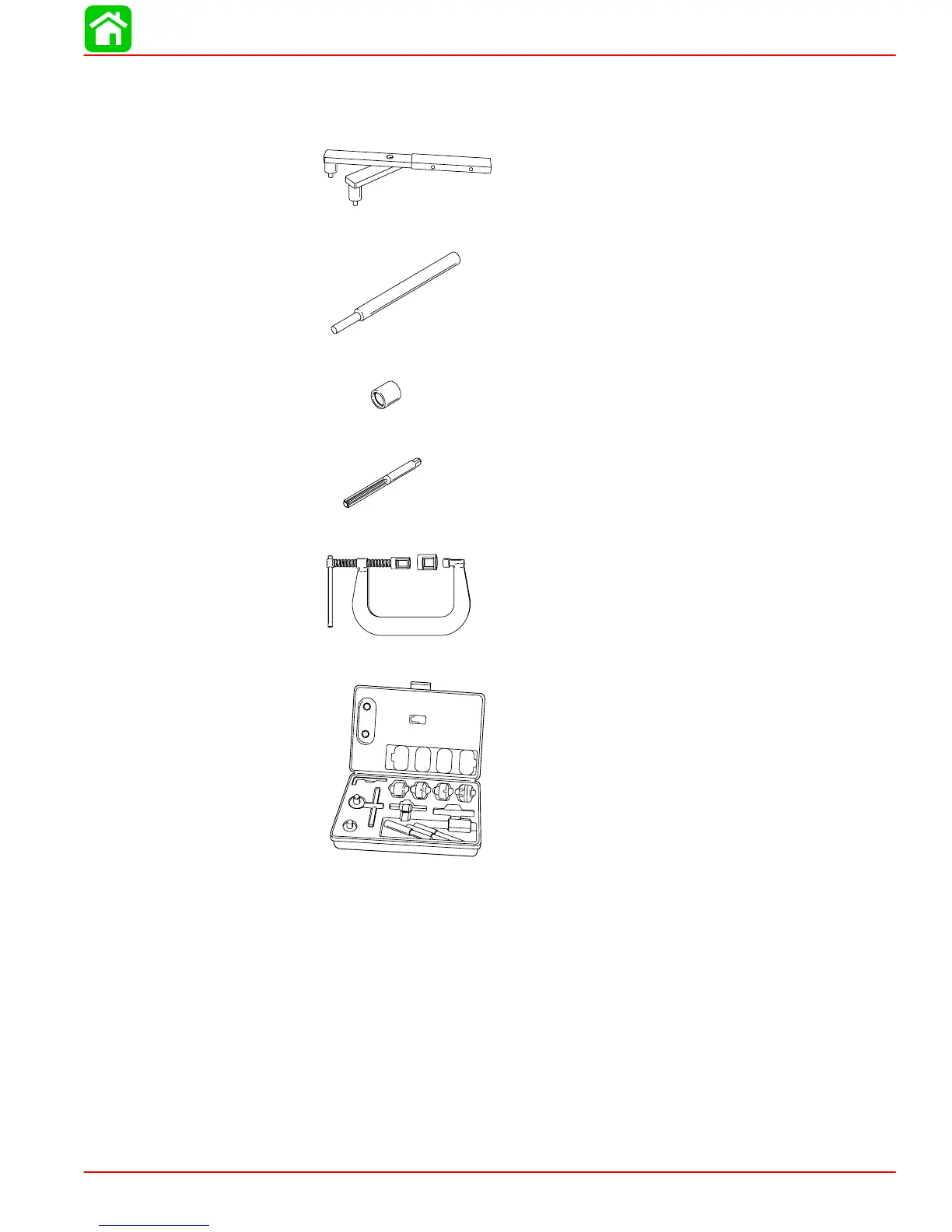
Special T
ools
1.
Flywheel Holder P/N 91-83163M
2.
V
alve Guide Remover P/N 91-809495A1
3.
V
alve Guide Installer Bushing P/N 91-809496A1
4.
V
alve Guide Reamer P/N 91-809497A1
5.
V
alve Spring Compressor P/N 91-809494A1
6.
V
alve Seat Cutter Kit (Obtain Locally).
221
223
Table of Contents
Important Information 1
20
Cleanliness and Care of Outboard Motor
3
Table of Contents
20
Special Tools
21
Mercury/Quicksilver Lubricants and Sealants 1B-2
21
Inspection and Maintenance Schedule
22
Before each Use
22
After each Use
22
Every 300 Hours of Use or Three Years
23
Before Periods of Storage
23
Flushing the Cooling System
23
Steering Link Rod Fasteners
24
Corrosion Control Anode
25
Spark Plug Inspection and Replacement
26
Battery Inspection
26
Fuse Replacement - Electric Start Models
27
Timing Belt Inspection
27
Lubrication Points
28
Checking Power Trim Fluid
29
Fuel System
30
Fuel Filter
30
Fuel Line Inspection
30
Changing Engine Oil
31
Oil Changing Procedure
31
Changing Oil Filter
32
Checking and Adding Engine Oil
32
Changing Gear Case Lubricant
33
3-1/4 In. (83Mm) Diameter Gear Case
33
4-1/4 In. (108Mm) Diameter Gear Case
34
Storage Preparation
36
Fuel System
36
Protecting External Outboard Components
36
Protecting Internal Engine Components
36
Gear Case
36
Positioning Outboard for Storage
37
Battery Storage
37
Important Information 1
38
Conditions Affecting Performance
39
Weather
39
Boat
40
Engine
42
Serial Number Location
39
Following Complete Submersion
43
Submerged While Running
43
Salt Water Submersion
43
Fresh Water Submersion
43
Model 30/40 (4-Stroke) Powerhead Views Front View
44
Starboard View
45
Port View
46
Top View
47
Aft View
48
Propeller Selection
49
Propeller Removal/Installation
50
3-1/4 In. (83Mm) Diameter Gear Case
50
4-1/4 In. (108Mm) Diameter Gear Case
51
Power Trim System
52
General Information
52
Power Trim Operation
52
Trim "In" Angle Adjustment
53
Trim Tab Adjustment
54
Compression Check
55
Cylinder Leakage Testing
56
Analysis
56
Water Pressure Measurement
57
Painting Procedures
58
Cleaning & Painting Aluminum Propellers & Gear Housings
58
Decal Removal/Application
59
Removal
59
Instructions for "Wet" Application
59
Important Information 1
61
Installation Specifications
62
Selecting Accessories for the Outboard
62
Start in Gear Protection
62
Lifting Outboard
63
Steering Cable
63
Steering Cable Seal
64
Steering Link Rod
64
Installing Outboard Thumb Screw Models
65
Wiring Harness
67
Battery Cable Connections
68
Shift and Throttle Cable Installation
69
Throttle Cable Installation
71
Trim Tab Adjustment
73
Trim-In Stop Adjustment Power Trim Models 1D-13
73
Instrument/Lanyard Stop Switch Wiring Diagram (Dual Outboard)
74
Electrical 2
76
Specifications
77
Special Tools
78
Flywheel
81
Electrical Components
83
Ignition Component Description
85
Electronic Control Module (ECM)
85
Crank Position Sensor
86
Stator Assembly
86
Flywheel Assembly
87
Ignition Coils
87
Ignition Description
85
Ignition Test Procedures
87
Direct Voltage Adapter (DVA)
87
Ignition Troubleshooting
88
Ignition Diagnostic Procedures
89
Recommended Test
90
Troubleshooting with the Digital Diagnostical Terminal
92
Using the Digital Diagnostical Terminal (DDT)
92
Component Resistance Tests
93
Spark Plug Cap Removal
94
Spark Plug Cap Resistor Test-P/N VDFP 2A-20
95
Spark Plug Cap Resistor Test P/N VDO5FP
95
Engine Coolant Temperature (ECT) Sensor
96
Flywheel Removal/Installation
97
Removal
97
Installation
99
Stator Removal/Installation
100
Timing Belt
101
Removal
101
Installation
102
ECM Removal/Installation
103
Ignition Coil Removal/Installation
104
Voltage Regulator Removal/Installation
105
Engine Coolant Temperature (ECT) Sensor Removal/Installation
107
Recommended Battery
110
Operating Engine Without Battery
110
Battery Charging System
111
Stator Ohms Test
115
Starting System Components
118
Troubleshooting the Starting Circuit
119
Brush Replacement
128
Electrical 2
143
30/40 Elpt
144
30/40 Ehpt
145
30/40 Mh
146
Commander 2000 Remote Control (Electric Start)
147
Commander 3000 Panel Mount Control
148
Instrument/Lanyard Stop Switch Wiring Diagram
149
Instrument/Lanyard Stop Switch Wiring Diagram (Dual Outboard)
150
Commander 2000 Key Switch Test
152
Instrument Wiring Connections
153
Without Light Switch
153
With Light Switch
153
Oil Pressure Wiring Diagram
154
QSI Gauge Wiring Diagrams
155
Tachometer Wiring Diagram
155
Water Temperature Gauge
156
Engine Synchronizer Wiring Diagram
157
Remote Wiring Harness Connection to Engine
160
Electric Start Remote Control Model
160
Remote Key
161
Power Trim Switch Wiring Diagram
162
Carburetor Adjustments
190
Idle Speed
190
Carburetor Removal
192
Carburetor Disassembly
193
Carburetor Reassembly
201
Carburetor Installation
206
Fuel System
208
Exhaust Emissions Standards
209
What Are Emissions
209
Hydrocarbons
209
Carbon Monoxide - CO
209
Oxides of Nitrogen - Nox
209
Controlling Emissions
209
Stoichiometric (14.7:1) Air/Fuel Ratio
210
Emissions Reductions
210
8 1/3% # Per Year over 9 Model Years
210
Outboard Hydrocarbon
210
Stratified Vs Homogenized Charge
211
Homogenized Charge
211
Stratified Charge
212
Emissions Information
213
Manufacturer's Responsibility
213
Dealer Responsibility
213
Owner Responsibility
213
EPA Emission Regulations
214
Decal Location for 1999 Models
215
Emission Control Information
215
Decal Location for 2000 and Newer Models
216
Service Replacement Certification Label
217
Powerhead
218
Specifications
219
Special Tools
222
Cylinder Head
223
Camshaft/Oil Pump
225
Intake/Exhaust Valves
227
Torque Sequence
229
Valve Cover
230
Removal
230
Installation
232
Valve Clearance Adjustment
235
Checking Valve Clearance
235
Adjusting Valves
236
Timing Belt
237
Removal
237
Installation
238
Cylinder Head Removal
239
Cylinder Head Disassembly
241
Rocker Arm Assembly Removal
241
Oil Pump Removal
241
Camshaft Removal
242
Valve Removal
243
Rocker Shaft and Rocker Arm
244
Cleaning/Inspection/Repair
245
Camshaft
245
Cylinder Head
247
Valve Guide Inspection
247
Valve Guide Replacement
248
Valves
249
Valve Springs
250
Valve Seat Reconditioning
252
Valve Refacing Steps
253
Cylinder Head Reassembly
254
Valve Installation
254
Camshaft Oil Seal Installation
255
Camshaft Installation
256
Oil Pump Installation
257
Rocker Arm Shaft Assembly
257
Rocker Arm Shaft Installation
258
Cylinder Head Gasket
259
Cylinder Head Installation
260
Powerhead
262
Specifications
263
Special Tools
264
Crankshaft
265
Cylinder Block and Crankcase
267
Torque Sequence
269
Powerhead Removal
270
Removing Powerhead Components
273
Cylinder Block Disassembly
274
Crankcase and Crankshaft Removal
275
Inspection
278
Cylinder Bore
278
Piston
279
Piston Pin
280
Piston Rings
280
Crankshaft
281
Checking Main Bearing Clearance
282
Checking Connecting Rod Bearing Clearance
284
Thermostat
285
Oil Pressure Switch
285
Cylinder Block Reassembly
286
Selecting New Main Bearings
286
Main Bearing Installation
287
Installing Connecting Rod Bearings
288
Connecting Rod Installation
289
Piston Ring Installation
290
Piston Installation
291
Crankshaft Installation
291
Crankcase Cover Installation
293
Thermostat and Exhaust Cover Installation
294
Drive Gear Installation
295
Installing Powerhead Components
296
Powerhead Installation
297
Tiller Handle Models
300
Transom Bracket
310
Swivel Bracket
312
Steering Arm
318
MID-Section
322
Special Tools
323
Power Trim
325
Adjustments
327
Trimming Characteristics
327
Trailering Outboard
328
Tilting Outboard up and down Manually
328
Theory of Operation
327
Power Trim Flow Diagrams
329
Trim up Circuit
329
Tilt Circuit
331
Maximum Tilt
333
Down Circuit
335
Shock Function
337
Shock Function Return
339
Manual Release
341
Troubleshooting
343
Preliminary Checks
343
Hydraulic System Troubleshooting Flow Chart
344
Troubleshooting the Power Trim Electrical System
348
Power Trim System Removal
350
Power Trim Disassembly
351
Trim Motor Removal
352
Pump and Components Removal
352
Manifold Removal
353
Shock Rod Removal
354
Shock Rod Disassembly
354
Memory Piston Removal
357
Cleaning/Inspection/Repair
358
Trim Motor Electrical Tests
358
Reassembly
359
O-Ring and Seal Placement
359
O-Ring Sizes
360
Power Trim Reassembly
362
Shock Rod Reassembly
362
Shock Rod Installation
364
Trim Limit Assembly Installation
365
Manual Release Valve Installation
365
Manifold Installation
366
Oil Pump Installation
367
Reservoir/Motor Installation
369
Bleeding Power Trim Unit
370
Installation of Power Trim System
370
MID-Section
374
Manual Tilt Components
375
Manual Trim Flow Diagrams
377
Up Circuit
377
Down Circuit
379
Slow Tilt down under High Thrust
381
Under Water Strike (Valves Open)
383
Shock Function (Valve Closed)
385
Shock Function Return
387
Hydraulic System Troubleshooting
389
Manual Tilt System Removal
391
Manual Tilt System Disassembly
393
Accumulator Removal
393
Shock Rod Removal
394
Shock Rod Disassembly
394
Valve Block Removal
397
Memory Piston Removal
398
Valve Block Disassembly
399
Reassembly - O-Ring and Seal Placement
400
Actual O-Ring Sizes
401
Manual Tilt System Reassembly
402
Valve Block Installation
405
Shock Rod Reassembly
406
Shock Rod Installation and Fluid Filling Procedure Option One
408
Fluid Filling Procedure Option Two
410
O-Ring Description and Sizes
402
Manual Tilt System Installation
413
Manual Release Valve Adjustment
416
Upper Drive Shaft Bearing
490
Oil Sleeve
491
Lower Drive Shaft Bearing Race
492
Forward Gear Bearing Race
495
Bearing Carrier Reassembly
499
Forward Gear Reassembly
503
Propeller Shaft Reassembly
505
Drive Shaft Wear Sleeve Installation
506
Oil Sleeve Installation
509
Tiller Handle
537
Tiller Handle Assembly Removal
539
Tiller Handle Disassembly
541
Cleaning/Inspection/Repair
543
Tiller Handle Reassembly
544
Tiller Handle Installation
549
Manual Starter
555
Interlock Cable Adjustment
557
Manual Starter Removal
558
Manual Starter Disassembly
559
Cleaning and Inspection
561
Rewind Starter Reassembly
562
Adjusting Rewind Spring Tension
563
Manual Starter Installation
567
30/40 (4-Stroke) Tiller Handle Electric
570
Wiring Diagram
570
30/40 (4-Stroke) Tiller Handle Manual
573
Wiring Diagram
573
30/40 (4-Stroke) Remote Control Electric
576
Wiring Diagram
576
30/40 (4 Stroke) Oil Flow Diagram
579
30/40 (4 Stroke) Water Flow Diagram
582
5
Based on 1 rating
Ask a question
Give review
Questions and Answers:
Need help?
Do you have a question about the Mercury 40 FourStroke and is the answer not in the manual?
Ask a question
Mercury 40 FourStroke Specifications
General
Brand
Mercury
Model
40 FourStroke
Category
Outboard Motor
Language
English
Related product manuals
Mercury 40 jet fourstroke
147 pages
Mercury 40
106 pages
Mercury 40 Jet
120 pages
Mercury Jet 40
61 pages
Mercury 40 SeaPro
104 pages
Mercury 40 4-Stroke
93 pages
Mercury 40/50 Series
152 pages
Mercury Marathon 40 HP
81 pages
Mercury 400R Verado FourStroke
144 pages
Mercury 15 FourStroke
128 pages
Mercury 150 FourStroke
136 pages
Mercury 25 EFI FourStroke
161 pages