CYLINDER HEAD
Page 4A-44 90-857046R1 NOVEMBER 2001
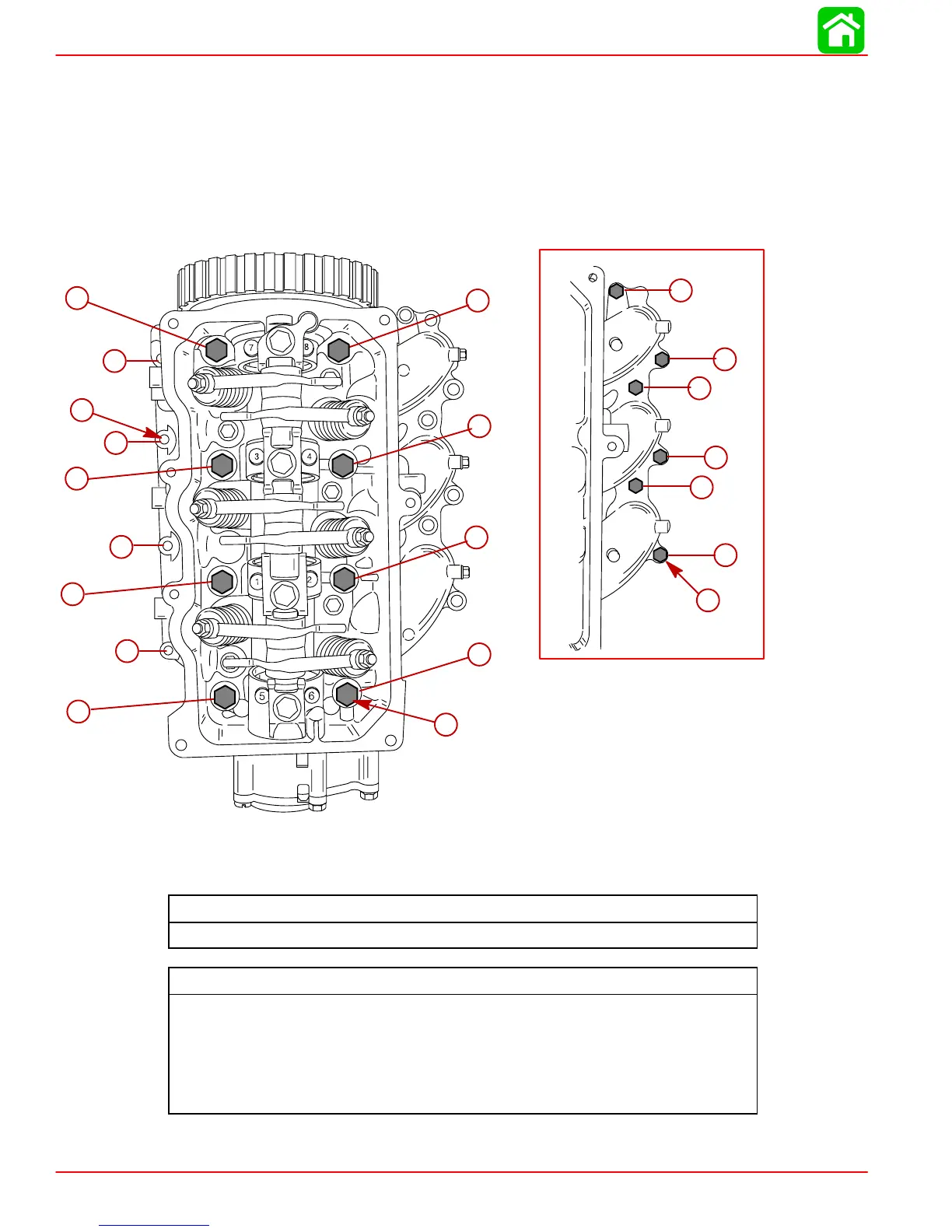
3. Torque center screws (first) in sequence and in two steps.
4. Torque the cylinder head and carburetor intake manifold screws in sequence and in two
steps.
5. Refer to “Timing Belt Installation” preceding, and install timing belt.
6. Refer to “Valve Clearance Adjustment” preceding, to perform valve clearance adjust-
ments.
7. Refer to “Valve Cover Installation” preceding, and install valve cover.
2
3
4
5
6
1
1
2
3
4
5
6
7
8
1
2
3
4
b
a
c
a-Center Screw (8) M9 x 95
b-Flange Screw (4) M6 x 25
c-Intake Manifold Screw (6) M6 x 25
Intake Manifold Screw Torque
70 lb. in. (8 N·m)
Cylinder Head Screw Torque
Center Screw (Qty. 8)
1st: 17 lb-ft (23 Nm)
2nd: 35 lb-ft (47 Nm)
Cyl. Head Flange Screw (Qty. 4)
1st: 53 lb-in. (6 Nm)
2nd: 106 lb-in. (12 Nm)