TILLER HANDLE
Page 7B-18 90-857046R1 NOVEMBER 2001
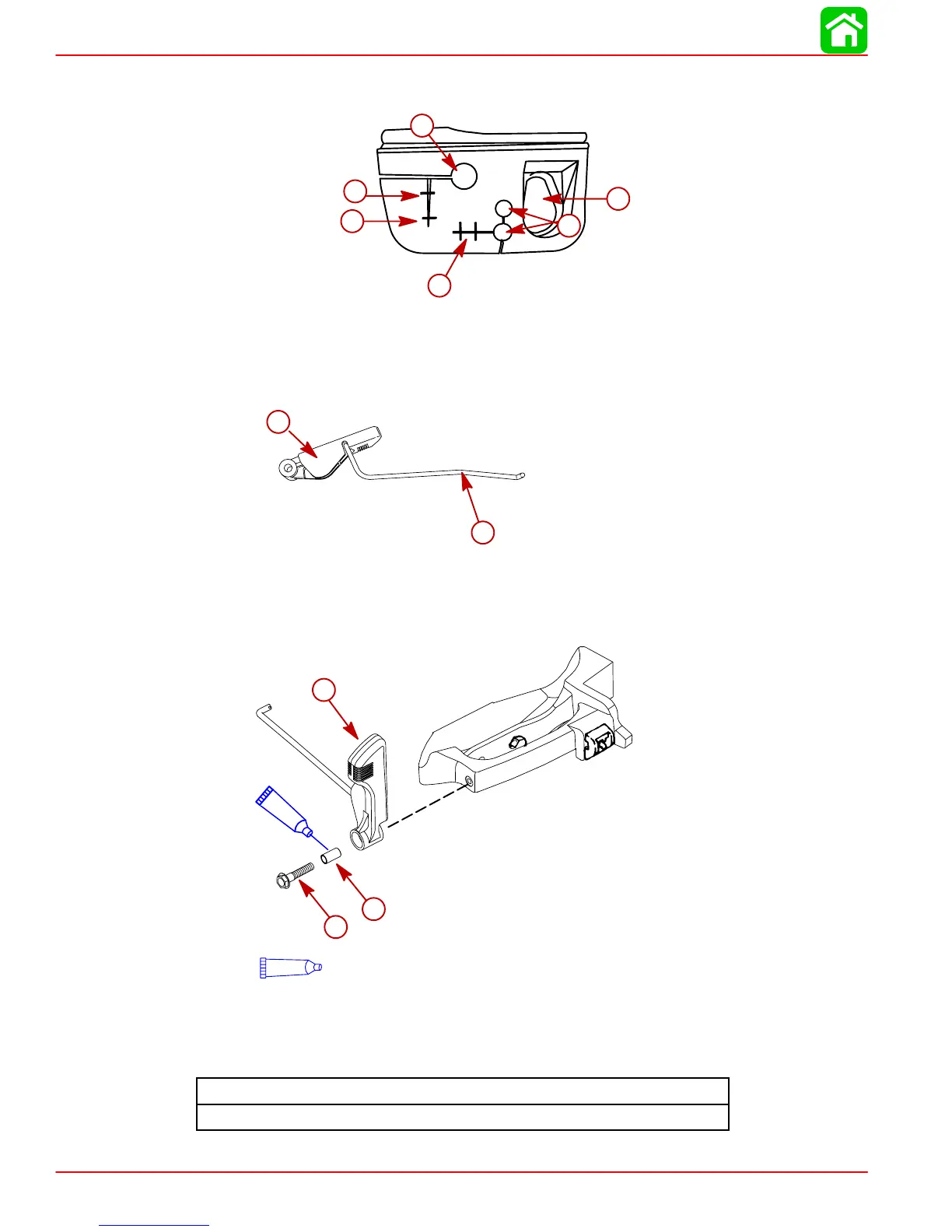
12. Cables, wires, and shift rod should be routed through grommet as shown. Seat grommet
between cowl halves.
a
b
c
d
e
f
a-Fuel Connector
b-Battery Cables
c-Throttle Cables
d-Shift Rod
e-Tiller Handle Harness Wires
f-Remote Key Harness
13. Assemble the shift rod into the shift handle by sliding the rod into the hole.
a
b
a-Shift Rod
b-Shift Handle
14. Install shift handle assembly, bushing, and screw. Tighten screw to specified torque.
95
95
2-4-C Marine Lubricant with Teflon
a
b
c
a-Handle Assembly
b-Screw M8 x 35
c-Bushing
Shift Handle Screw Torque
100 lb. in. (11.3 N·m)

 Loading...