Millipore System Documentation Set
26 Operating and Maintenance Manual Publication XITXSP121 P Rev.A
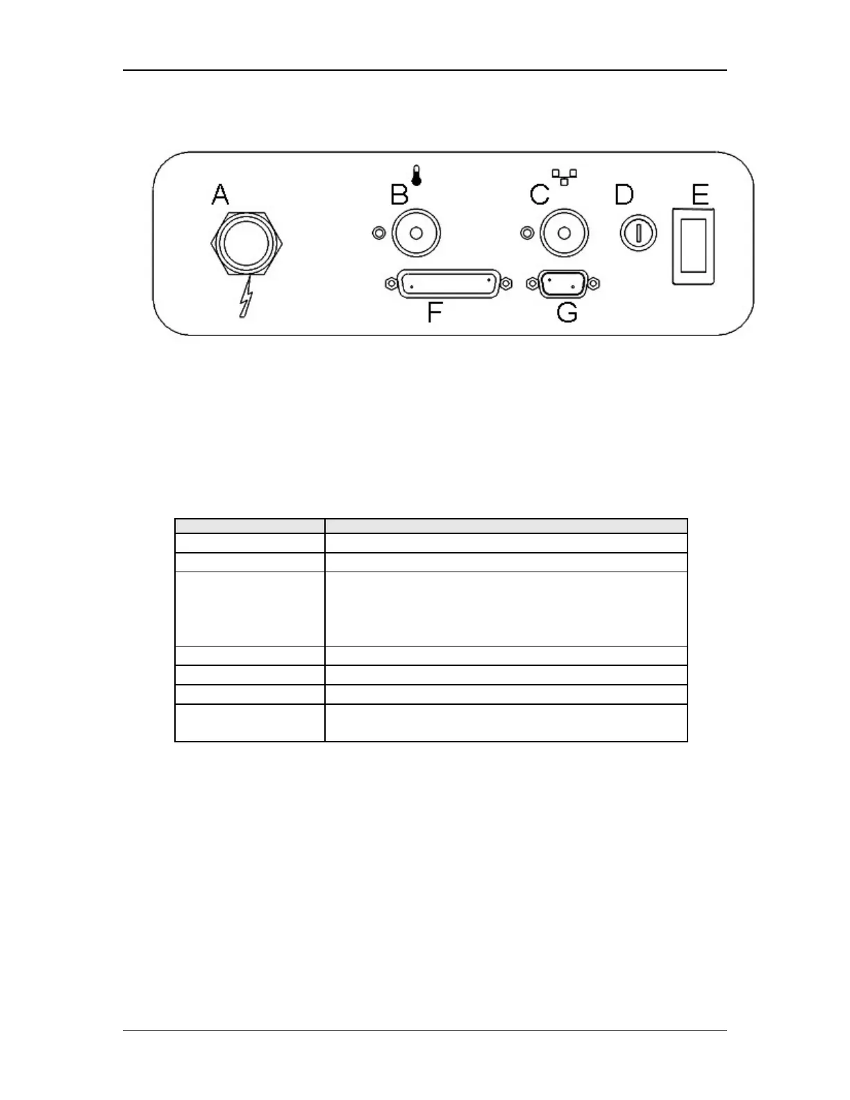
Electrical Connections
Diagram Key: A. Power Inlet E. System On/Off
B. Housing Temperature F. Parallel Port
C. Network G. 1010 Serial Port
D. Fuse 2A 250V IEC 127-2/III
Figure 3: Rear Panel
Table 1: Electrical Connections
Label Description
Power inlet Power cord connector
Housing Temp Housing Gas Temperature Sensor, optional
Network Watertight Ethernet network connector designed to
connect to a Millipore Adapter. The Millipore Adapter
is 6-ft. watertight cable designed for conversion to
standard 10BASE-T connection. (Optional)
Fuse access 2 amp, slow blow (delayed action), 250v, 5 x 20 mm
System on/off Power switch
Parallel LPT1, parallel port for external Line Printer, optional
Serial RS232 or RS485/422 serial port designed for future
applications, optional
See the Maintenance and Calibration section (page 177) for details about:
• Changing the fan filter
• Changing the gas inlet filter
• Changing the fuse
See the Printing section (page 133) for details about
• Replacing the Ink Cartridge (page 146)
• Changing the Paper (page 145)
Power Cord Assembly
Two power cords are provided with the instrument. The 110 volt power cord is terminated with
a standard North American Nema 5-15P plug, and the 240 volt power cord is shipped with