Millipore System Documentation Set
28 Operating and Maintenance Manual Publication XITXSP121 P Rev.A
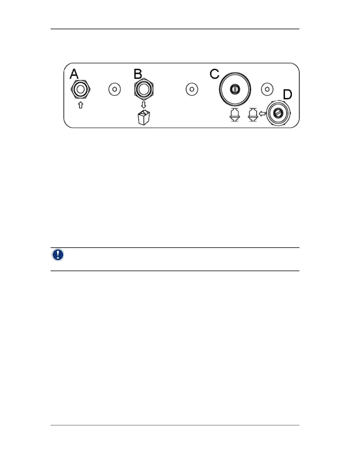
Pneumatic Connections
Diagram Key: A. Gas Inlet (see Gas Supply Requirements below)
B. Exhaust
C. From Housing
D. To Housing
Figure 4: Side Panel
• Gas Inlet (quick disconnect labeled “Air Inlet”)
• Exhaust (tubing connector)
• Outlet (dual quick disconnects labeled “From Housing” and “To Housing”)
Gas Supply Requirements
The instrument must be connected to a regulated supply of clean dry air (>-20 C dew point) or
nitrogen at 35–120 psig (2.4–8.5 bar).
Note: To minimize the likelihood of water contamination, it is recommended that the inlet
gas be filtered with an external coalescing filter.
Gas Inlet Connection
To Gas Supply
• Do not remove the gas inlet filter or damage to the instrument may result.
• Connect a regulated supply of clean dry air or nitrogen, 35–120 psig (2.4–8.5
bar), to the inlet tubing assembly of the instrument using the ¼” NPTF side of the
gas filter.
• Supply at least 15 psi (1.02 bar) more than the maximum pressure required to
perform the filter test.
To Instrument
• Slide quick disconnect fitting of Integritest Exacta inlet tubing assembly onto the
connector stem labeled Air Inlet.
• Grasp the rear of the connector and push it firmly against the connector stem. Do
not grasp the flared section when making a connection. This section must be able
to slide freely into place
• Release it when you hear it click into place.