Integritest Exacta Filter Integrity Test Instrument
Operating and Maintenance Manual Hardware Connections 31
C. Liquid Trap F. Gas Inlet
*optional item
Figure 6: Inlet and Outlet Tubing Connections
To Disconnect the Tubing
• Push the collar of the fitting towards the instrument (see Figure 5).
• Gently pull the tubing away from the instrument. (see Figure 5).
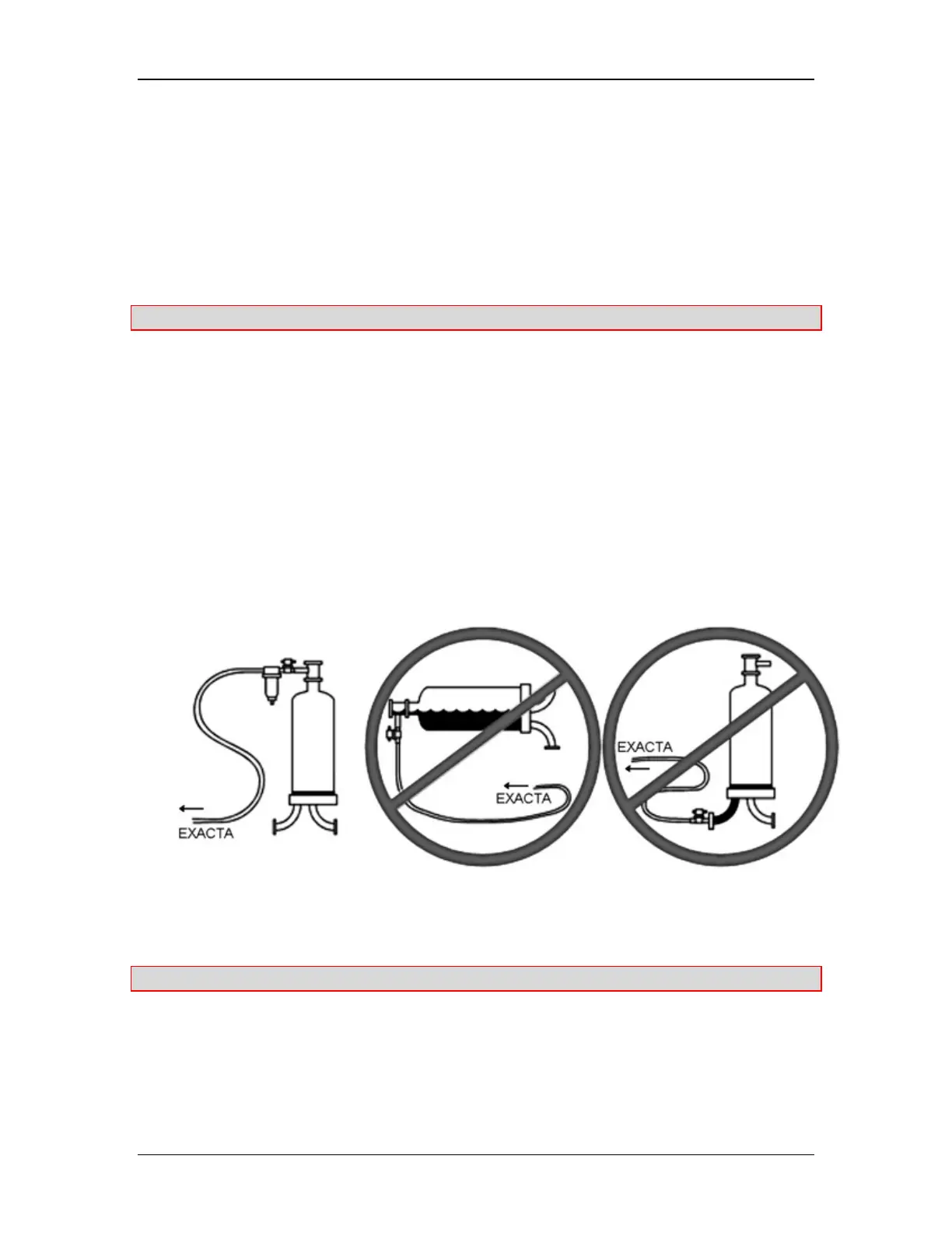
WARNING: Proper Installation is required
When installing the Integritest Exacta instrument, you must attach the outlet tubing assembly
and instrument valve to the top of the filter housing. The filter housing must be perpendicular
to the floor (Figure 7). For example, when using a T-line housing, you cannot attach the tubing
assembly to the housing inlet, which is located below the filter.
If the tubing assembly and instrument valve are not installed at the top of the housing, during
integrity testing residual fluid in the housing could be drawn back into the instrument when the
system is exhausted, and may cause damage to the instrument.
An improper installation of the outlet tubing assembly and instrument valve
to the filter housing will void your warranty. Incorrect installation includes installing
the tubing assembly and the instrument valve below the filter or onto a filter housing that is not
upright.
CORRECT INCORRECT INCORRECT
Figure 7: Correct Filter Housing Assembly
Warning: Make sure all connections are tight before continuing.
Cutting the Tubing
1. Cut the tubing squarely (See Figure 8).