NICE3000
new
User Manual 8 Description of Function Codes
- 213 -
8.7.4 Terminal State Display
Function Code Parameter Name Setting Range Default Unit Property
F5-34
Terminal state display Monitoring of I/O terminals on MCB - -
●
F5-35
Terminal state display
Monitoring of I/O terminals on CTB,
CCB and HCB
- -
●
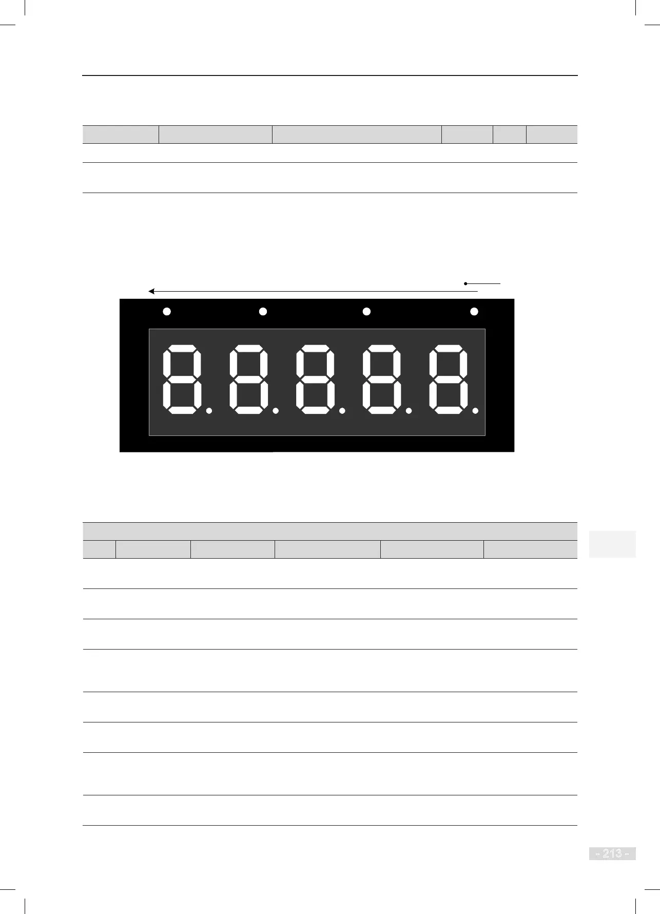
These parameters are used to monitor the state of all I/O terminals of the system.
The segments of the ve LEDs displayed are dened as follows.
Figure 8-11 Monitoring of all I/O terminals
RUN
LOCAL/REMOT FED/REV TUNE/TC
5 4 3
2
1
A
B
C
D
E
F
G
DP
Note:
1. Segments of LEDs 2 to 5 are marked in the same way as those of LED 1.
2. Segment ON: signal active
Segment OFF: signal inactive
LED No.
F5-34 Terminal state display
1 2 3 4 5
A - Inspection signal Up slow-down 1 signal
Door machine 1 light
curtain
Reserved
B
Up leveling
signal
Inspection up
signal
Down slow-down 1
signal
Door machine 2 light
curtain
RUN contactor
output
C
Down leveling
signal
Inspection down
signal
Up slow-down 2 signal
Brake contactor
feedback 2
Brake contactor
output
D
Door zone
signal
Fire emergency
signal
Down slow-down 2
signal
UPS input
Shorting door lock
circuit contactor
control
E
Safety circuit
feedback 1
Up limit signal Up slow-down 3 signal Elevator lock input
Fire emergency
oor arrival signal
F
Door lock circuit
feedback 1
Down limit signal
Down slow-down 3
signal
Safety circuit feedback
2
-
G
RUN contactor
feedback
Overload signal
Shorting door lock
circuit contactor
feedback
Shorting PMSM stator
contactor feedback
-
DP
Brake contactor
feedback 1
Full-load signal
Fireghter running
signal
Door lock circuit
feedback 2
-