NICE3000
new
User Manual
4 Peripheral Devices and Options
- 93 -
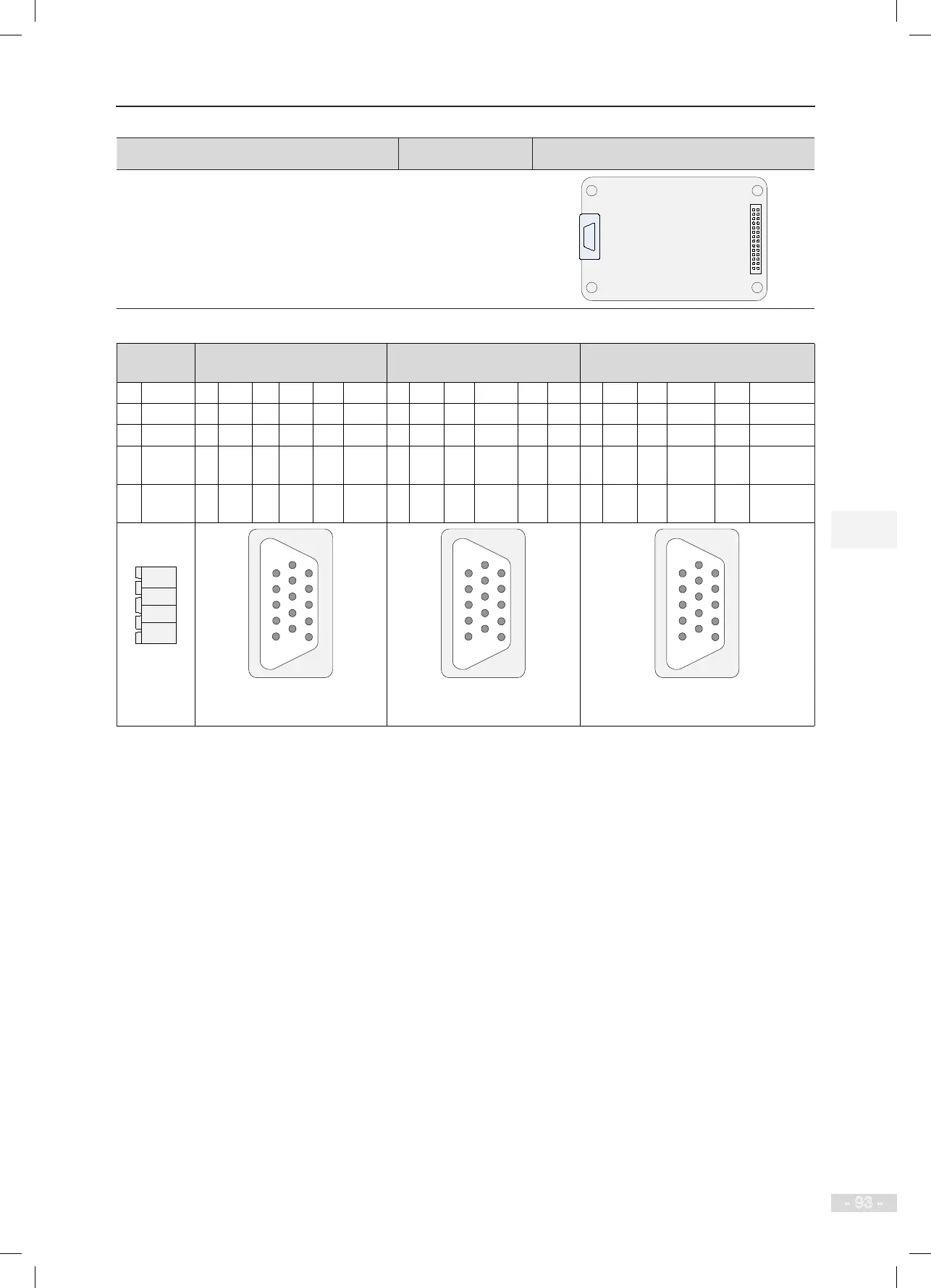
Encoder Type Adaptable PG Card Appearance
Absolute encoder (ECN413/1313) MCTC-PG-F1
Table 4-22 Denitions of the CN1 terminals of different MCTC-PG card models
MCTC-
PG-A2
MCTC-PG-D MCTC-PG-E MCTC-PG-F1
1 15V 1 A+ 6 NC 11 W+ 1 B- 6 A- 11 C- 1 B- 6 A- 11 CLK-
2 PGM 2 A- 7 U+ 12 W- 2 NC 7 COM 12 D+ 2 NC 7 GND 12 DATA+
3 PGA 3 B+ 8 U- 13 VCC 3 Z+ 8 B+ 13 D- 3 NC 8 B+ 13 DATA-
4 PGB 4 B- 9 V+ 14 COM 4 Z- 9 VCC 14 NC 4 NC 9
5V
(Up)
14 NC
5 NC 10 V- 15 NC 5 A+ 10 C+ 15 NC 5 A+ 10 CLK+ 15
5V
(Sensor)
CN1
CN1
CN1
CN1
4.5.2 Connection Between PG Card and Encoder
The MCTC-PG card is connected to the controller and the encoder as follows:
The J1 terminal and CN1 terminal of the MCTC-PG card are respectively connected to the J12 terminal of
the MCB on the controller and the encoder of the motor.
Different MCTC-PG card models are connected to the MCB in the same way. The connection method to
the encoder depends on the CN1 terminal of the model.
The following gure shows connections between MCTC-PG-E and the controller.