3 Mechanical and Electrical Installation NICE3000
new
User Manual
- 46 -
Mark Terminal Name Function Description
232
Serial communication
indicator
This indicator is on (green) when communication with the host
computer or cell/remote monitoring board is normal.
X1 to X24 Input signal indicator This indicator is on when the external input is active.
Y1 to Y6 Output signal indicator This indicator is on when the system output is active.
◆
Control Circuit Wiring
● Cable selection for control circuit
Use copper conductors of a proper size as control cables according to the recommended
values in Table 4-2.
● Cabling requirement of control circuit
The motor cables must be laid far away from all control cables.
It is recommended that the motor cables, power input cables and control cables be laid in
different ducts. To avoid electromagnetic interference caused by rapid change of the output
voltage of the controller, the motor cables and other cables must not be laid side by side for a
long distance.
If the control cable must run across the power cable, make sure they are arranged at an angle
of close to 90°.
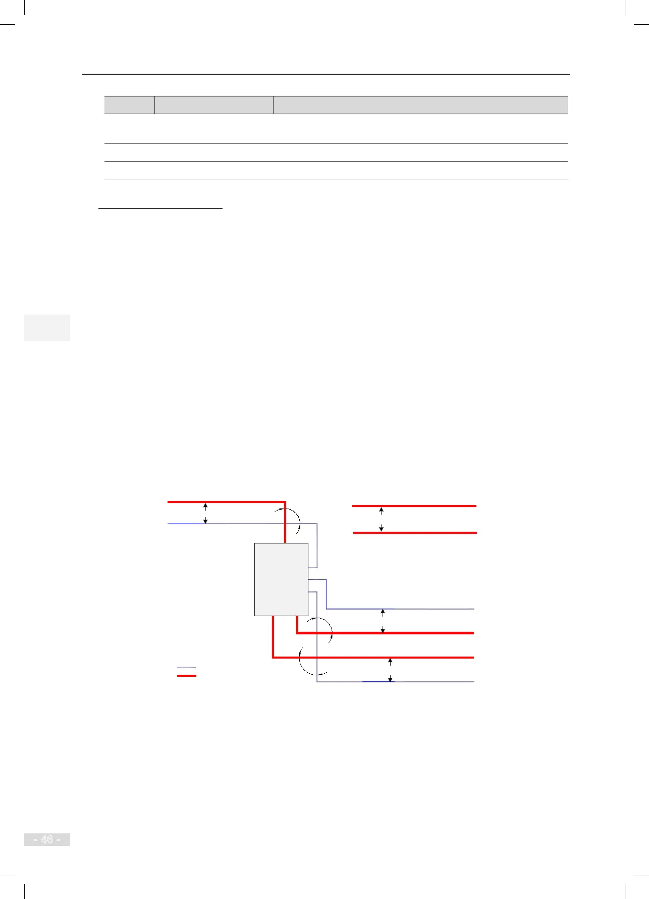
The following gure shows the recommended cabling diagram.
Figure 3-20 Cabling diagram
NICE3000
new
integrated
elevator
controller
Min. 200 mm
Min. 300 mm
Power cable
Motor cable
Min. 500 mm
Min. 500 mm
Regen. resistor cable
Motor cable
Power cable
90°
90°
90°
Control cable
Control cable
Power cable
Control cable
Control cable
3.2.5 Control Circuit Cable Sizes and Tightening Torque
Use the tubular terminal with the insulation sleeve.
When the single cable or twisted pair is used, the cable end must be exposed by 6 mm.