NICE3000
new
User Manual
3 Mechanical and Electrical Installation
- 45 -
Mark
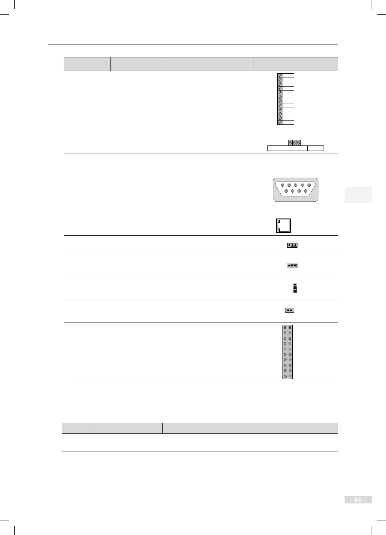
Code Terminal Name Function Description Terminal Arrangement
CN7
Y1/M1 to
Y6/M6
Relay output
NO, maximum current and voltage
rating: 5 A, 250 VAC
Function set in F5-26 to F5-31
CN7
Y1
M1
Y2
M2
Y3
M3
Y4
M4
Y5
M5
Y6
M6
CN4 CAN2+/-
CAN2 differential
signal
CAN2 communication interface,
used for parallel/group control
CN5
DB9
interface
RS232
communication
interface
Interface for:
Commission software community
monitoring
RS232/RS485 parallel/group
control
Software download of the MCB
and drive board
CN12
RJ45
interface
Operation panel
interface
Used to connect the external
operation panel
J1
Optional grounding terminal for
AI
The pins marked with “COM” are
connected to the ground.
J5
Termination resistor connection
terminal for the CAN1
communication control board
The pins marked with “ON” are
connected to the termination
resistor.
J6
Termination resistor connection
terminal for the CAN2
communication control board
The pins marked with “ON” are
connected to the termination
resistor.
J7
Grounding terminal of the
control board.
If it is shorted, the ground of the
control board is connected to the
ground of the controller.
J12
Interface for connecting the PG
card
-
J9/J10 Factory reserved
Do not short them randomly.
Otherwise, the controller may not
work properly.
-
Table 3-9 Description of indicators on the MCB
Mark Terminal Name Function Description
COP
CAN1 communication
indicator
When communication between the MCB and the CTB is normal, this
indicator is on (green).
HOP
Modbus communication
indicator
When communication between the MCB and the HCB is normal, this
indicator is on (green).
CAN2
Group control
communication indicator
This indicator is steady on (green) when communication for parallel/
group control is normal, and blinks when the running in parallel/group
mode is normal.