3 Mechanical and Electrical Installation NICE3000
new
User Manual
- 58 -
unnecessary resistor is connected besides the termination resistors at two ends. In this case, you
need to disconnect this unnecessary resistor.
●
Check the communication cable.
The communication cable must be twisted pair with metal shield. The cable sectional area is 0.75
mm
2
at minimum. All common terminals COM are connected together (not connect to the system
grounding cables). The power supply of all the nodes must be grounded reliably.
●
Check with us whether the protocol is customized special protocol.
3.4 Installation of Shaft Position Signals
In elevator control, to implement landing accurately and running safely, the car position needs to be
identied based on shaft position signals.
These shaft position signals include the leveling switches, up/down slow-down switches, up/down limit
switches, and up/down nal limit switches.
These shaft position signals are directly transmitted by the shaft cables to the MCB of the controller. For
the electrical wiring method, refer to Figure 3-11.
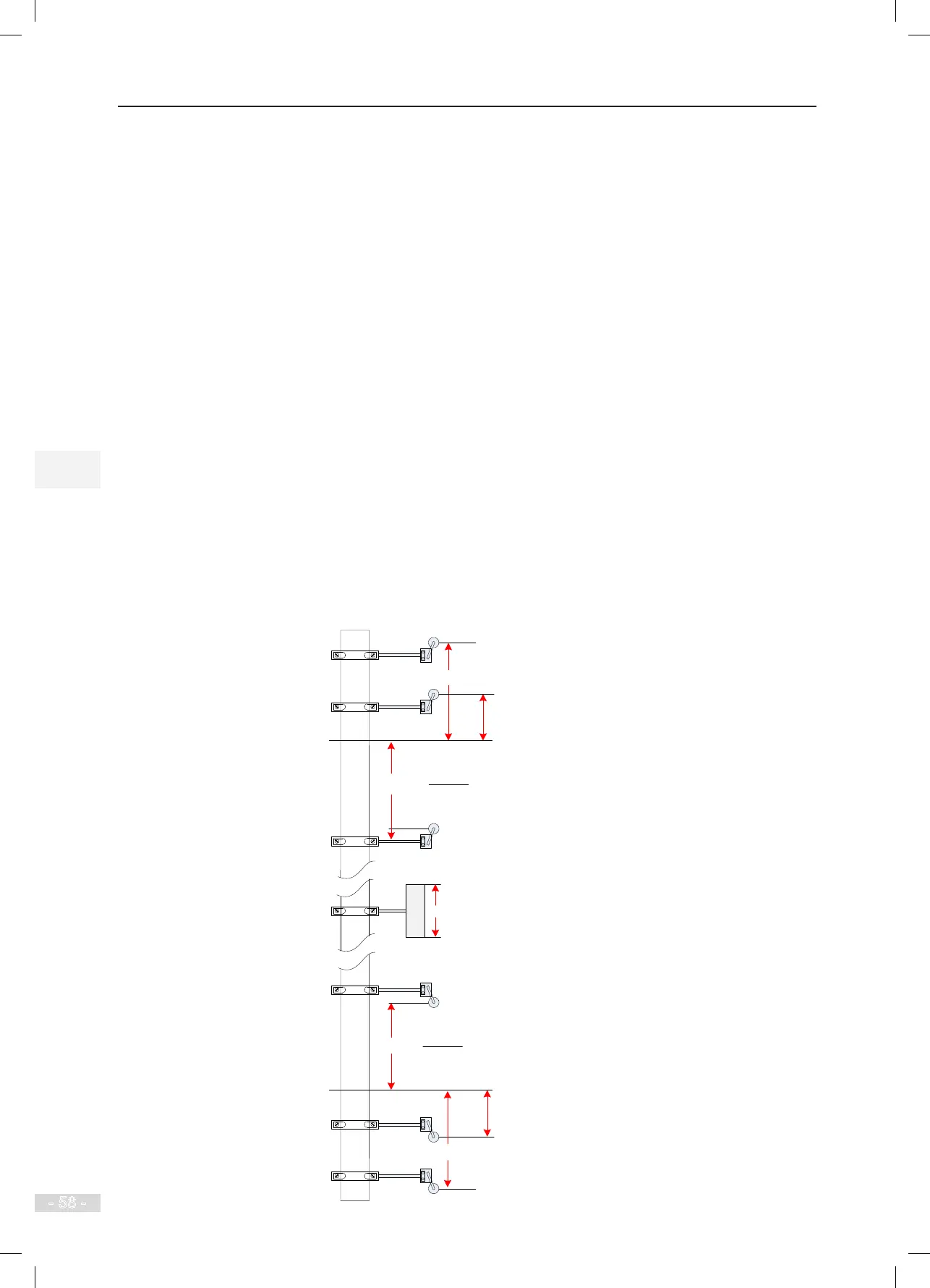
The following gure shows the arrangement of shaft position signals in the shaft.
Figure 3-35 Arrangement of shaft position signals
Leveling plate
(floor N)
L
80 ≤ D ≤
200 mm
150 mm
L >
2 x F3-08
V²
Top leveling
position
D
L
150 mm
Up final limit
switch
Up limit
switch
30-50 mm
(V: Rated elevator speed)
Up slow-down switch
Down slow-down switch
Bottom leveling
position
Down limit
switch
Down final
limit switch
30─50 mm
L >
2 x F3-08
V²
(V: Rated elevator speed)