NICE3000
new
User Manual
4 Peripheral Devices and Options
- 89 -
No. Interface Pins 2 and 3 Pins 1 and 4 Remarks
Note: Pins 1 and 2 are positive of power supply. The pin with white dot mark or that is rectangular is pin 1.
● Perform wiring strictly according to the terminal marks and ensure that the button is inserted securely.
● The MCTC-CCB has the same interfaces on both ends, and do not make wrong connection when
connecting multiple boards in series.
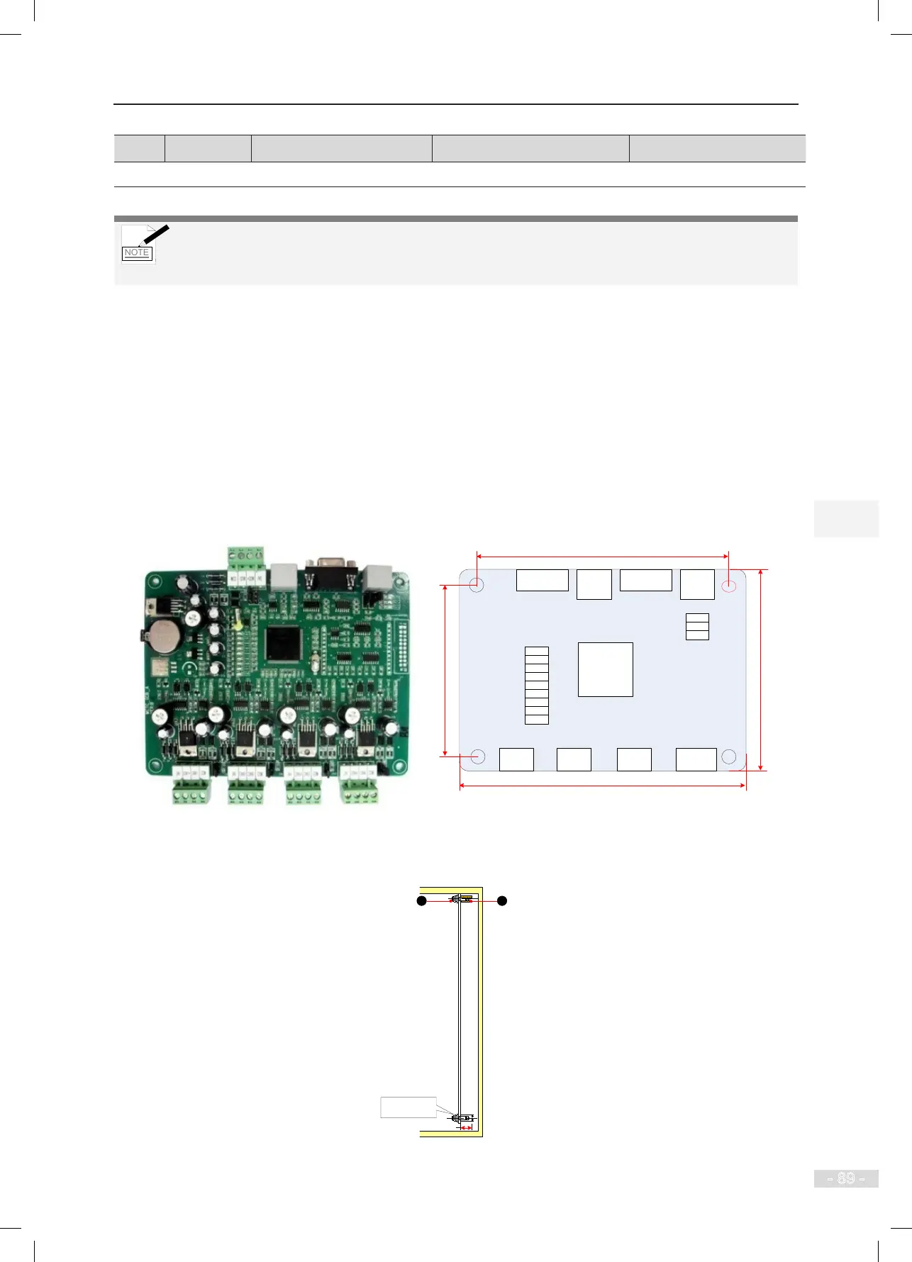
4.4.4 GCB Board (MCTC-GCB)
With together use of the group control board (GCB), the NICE3000
new
supports group control of elevators.
A single GCB (standard program) supports group control of 4 elevators, with a maximum of 40 oors.
Combination of two GCBs (customized program) supports group control of 5 to 8 elevators, with a
maximum of 40 oors; for details on the customized program, contact us.
The following gure shows the appearance and dimensions of the GCB.
Figure 4-22 Appearance and dimensions of the GCB
152
162
115
125
CN2
CN1
CN7 CN8 CN10CN9
CPU
CN3
CN6
D5
D2
D3
D37
D40
D44
D43
D42
D41
D45
D46
D47
Unit: mm
MCTC-GCB
The following gure shows the installation method of the GCB.
Figure 4-23 Installation method of the GCB
MCTC-GCB
Combination
screw M4x10
8.8
Unit: mm
1 - Plastic support higher than 1 cm
2 - Combination screw M4x10
1
2