4 Peripheral Devices and Options NICE3000
new
User Manual
- 90 -
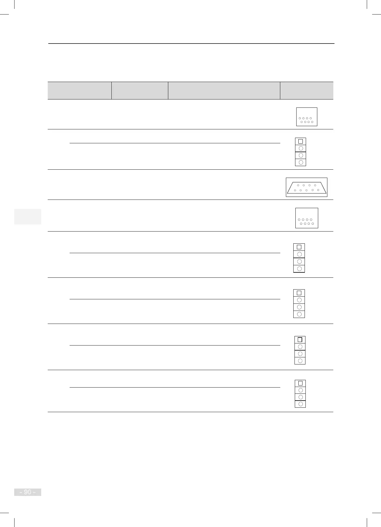
The following table describes the input and output terminals of the GCB.
Table 4-20 Input and output terminals of the GCB
Mark Terminal Name Function Description
Terminal
Arrangement
CN1
Operation panel
interface
Connecting the external operation panel
CN2
+24V/COM 24 VDC output 24 VDC power supply for the entire GCB
MOD+/MOD-
Modbus
communication
terminal
LCD display and extension functions
CN3 232 interface Communicating with the host computer.
CN6 Reserved -
CN7
+24V/COM
External 24 VDC
power supply
24 VDC power supply for the corresponding
CANbus communication module
CAN1+/CAN1-
CANbus
communication
terminal
CANbus communication between the GCB
and the MCB of each elevator in group
control
CN8
+24V/COM
External 24 VDC
power supply
24 VDC power supply for the corresponding
CANbus communication module
CAN2+/CAN2-
CANbus
communication
terminal
CANbus communication between the GCB
and the MCB of each elevator in group
control
CN9
+24V/COM
External 24 VDC
power supply
24 VDC power supply for the corresponding
CANbus communication module
CAN3+/CAN3-
CANbus
communication
terminal
CANbus communication between the GCB
and the MCB of each elevator in group
control
CN10
+24V/COM
External 24 VDC
power supply
24 VDC power supply for the corresponding
CANbus communication module
CAN4+/CAN4-
CANbus
communication
terminal
CANbus communication between the GCB
and the MCB of each elevator in group
control