8 Description of Function Codes NICE3000
new
User Manual
- 210 -
the HCB.
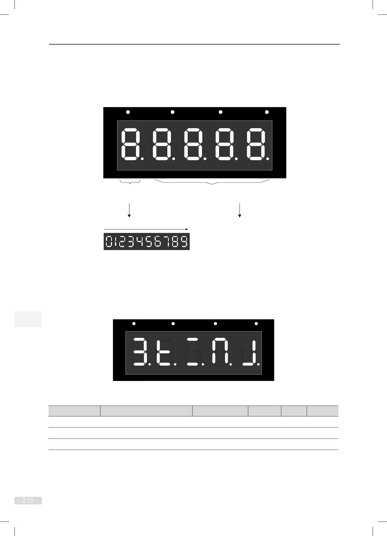
When you enter the menu of F5-32, the LEDs on the operation panel indicate the current HCB
communication state.
Figure 8-5 F5-32 communication state monitoring
Segment No. indicates the address of the HCB at
each floor for Modbus communication with the MCB.
CANbus communication state from strong to weak
Best
Interrupted
Monitoring CANbus
communication state
between the CTB and the MCB
Segment ON: communication normal
Segment OFF:
communication abnormal
1
2
35
6
4
7
8
9
10
11
15
12
13
14
16
17
23
18
19
20
21
2226
27
28
29
24
25
30
31
RUN
LOCAL/REMOT FED/REV TUNE/TC
For example, if the LEDs are shown as the following gure, it indicates that Modbus communication of
addresses 1, 5, 6, 7, 12, 15, 16, 18, 19, 21, 22, 23, 25, 26 and 27 is abnormal, and Modbus communication
of other addresses is normal. CANbus communication state displayed by the LED is 3, indicating normal
communication.
Figure 8-6 Example of LED display indicating the communication state
1
2
35
6
4
7
8
9
10
11
15
12
13
14
16
17
23
18
19
20
21
2226
27
28
29
24
25
30
31
RUN LOCAL/REMOT FED/REV TUNE/TC
8.7.2 HCB Communication State Display
Function Code Parameter Name Setting Range Default Unit Property
FA-46
HCB communication state 1 0–65535 0 -
●
FA-47
HCB communication state 2 0–65535 0 -
●
FA-48
HCB communication state 3 0–65535 0 -
●
These parameters display the communication state between HCBs of all oors and the MCB.
FA-46, FA-47, and FA-48 respectively indicate the communication state of oors 1 to 16, 17 to 32, and 33
to 40.