5 Use of the Commissioning Tools NICE3000
new
User Manual
- 102 -
A
B
C
D
E
F
G
DP
A
B
C
D
E
F
G
DP
A
B
C
D
E
F
G
DP
3
2
1
Segment ON: signal active
Segment OFF: signal inactive
1 2 3
A
B
C
D
E
F
DP
Light curtain 2 input
Door open limit 1 input
Door open limit 2
input
Door close limit 1 input
Door close limit 2 input
Full-load input
Overload input
Light-load
-
-
-
-
-
-
Door open 1 output
Door close 1 output
Forced door close 1 output
Door close 2 output
Forced door close 2 output
Up arrival gong output
Down arrival gong output
Light curtain 1 input
- Door open
2 output
G
●
FC: elevator direction change (same as the function of F2-10)
0: Direction unchanged
1: Direction reversed
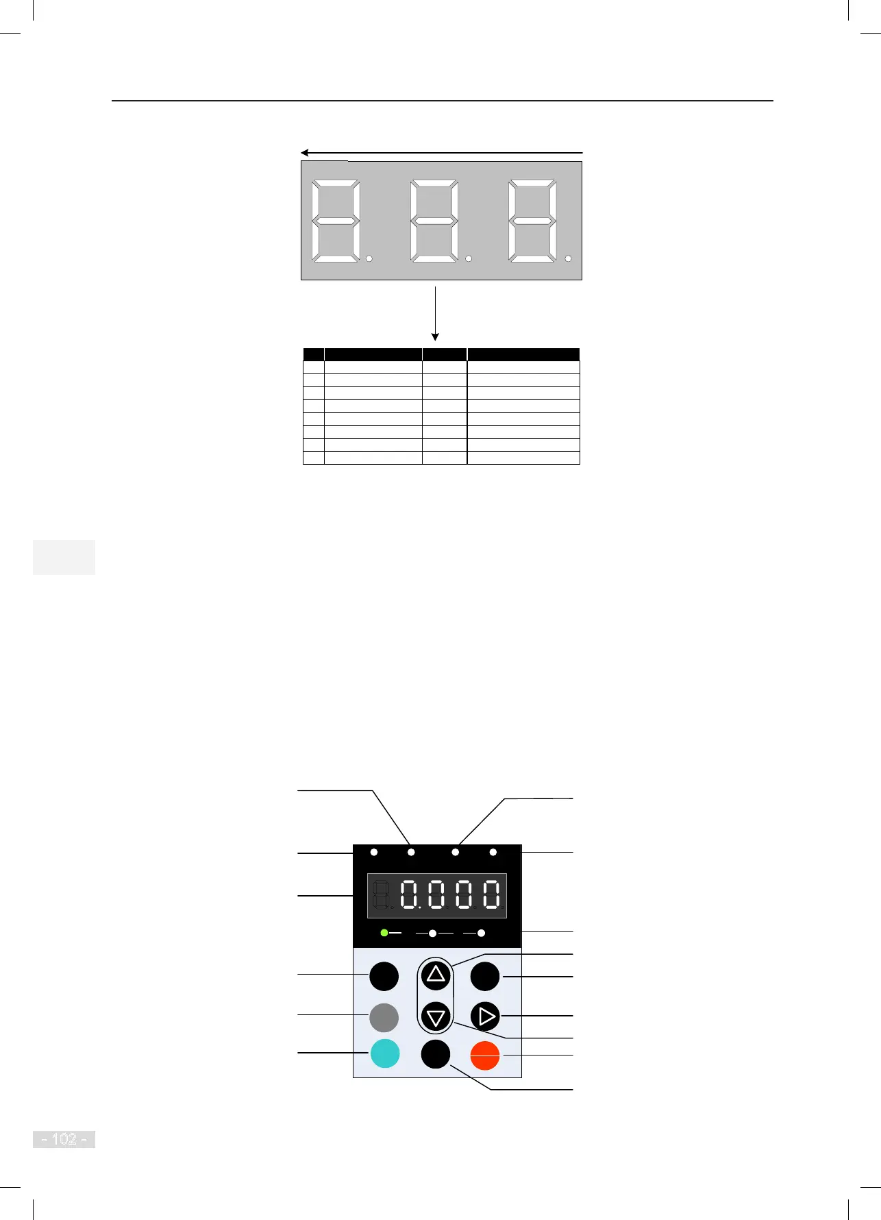
5.2 Use of the LED Operation Panel (MDKE)
5.2.1 Introduction to the Operation Panel
The LED operation panel is connected to the RJ45 interface of the controller by using an 8-core at cable.
You can modify the parameters, monitor the working status and start or stop the controller by operating the
operation panel. The following gure shows the LED operation panel.
Figure 5-3 LED operation panel diagram
MF.K
RUN
STOP
RES
QUICK
PRG ENTER
RUN
LOCAL/ REMOT FED/REV TUNE/TC
RPM
%
A VHz
Reserved
Up/Down indicator
RUN indicator
Auto-tuning indicator
Data display
Programming key
RUN key
Menu key
Fault hiding key
Stop/Reset key
Shift key
UP key
Down key
Confirm key
Unit indicator
ON: down direction
OFF: up direction