NICE3000
new
User Manual
3 Mechanical and Electrical Installation
- 47 -
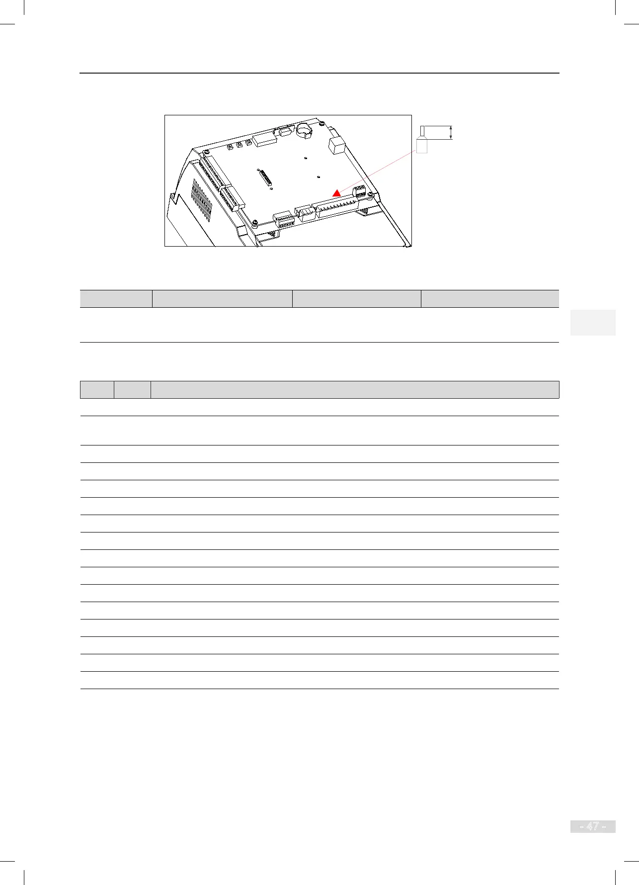
Figure 3-21 Control circuit tubular terminal requirement
Table 3-10 Control cable specications
Single Cable mm² (AWG) Twisted Pair mm² (AWG) Torque of Torque Driver (N·m)
Control circuit
terminal block
0.2–0.75
(AWG24–18)
0.565
3.2.6 Wiring Checklist
□√
No. Item
□ 1 Check the controller model to ensure receipt of correct model.
□ 2 The peripheral devices (braking components, AC reactor, lter, and circuit breaker) meet the
requirements.
□ 3 Check the optional board models to ensure receipt of correct model.
□ 4 The installation method and environment of the controller meet the requirements.
□ 5 Test that the input voltage is within 380–440 V.
□ 6 The rated motor voltage is consistent with the output ratings of the controller.
□ 7 Wire the power input cables to R, S, T terminals of the controller correctly.
□ 8 Wire motor cables to U, V, W terminals of the controller correctly.
□ 9 The cable size of the main circuit meets the requirements.
□ 10 Check whether the motor cables exceed 50 m. If yes, decrease the carrier frequency set in F0-07.
□ 11 Check whether the grounding cable is grounded properly.
□ 12 The output terminals and control circuit terminals are wired securely.
□ 14 Check correct wiring of the braking components and proper resistance of the regen. resistor.
□ 16 The control circuit signal cables use the shielded twisted pair.
□ 17 The optional boards are wired correctly.
□ 18 The control circuit cables are separated from the main circuit cables during cabling.