3 Mechanical and Electrical Installation NICE3000
new
User Manual
- 60 -
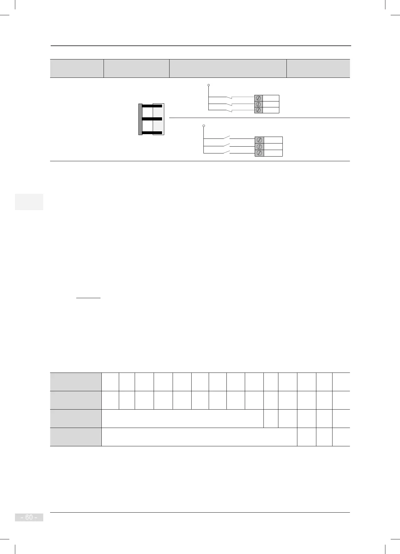
Number of
Leveling Switches
Installation Method Connecting to Input Terminals of Controller
Setting of Function
Code
3
Door zone
signal detection
Up leveling
signal detection
Down leveling
signal detection
Up leveling
X1
X2
X3
+24 VDC
Door zone signal
Down leveling
F5-01 = 33 (NC)
F5-02 = 35 (NC)
F5-03 = 34 (NC)
Down leveling
Up leveling
X1
X2
X3
+24 VDC
Door zone signal
F5-01 = 01 (NO)
F5-02 = 03 (NO)
F5-03 = 02 (NO)
3.4.2 Slow-Down Switches
The slow-down switch is one of the key protective components of the NICE3000
new
, protecting the elevator
from over travel top terminal or over travel bottom terminal at maximum speed when the elevator position
becomes abnormal.
The NICE3000
new
system supports a maximum of three pairs of slow-down switches. The slow-down switch
1, slow-down switch 2 and slow-down switch 3 are installed from the two ends of the shaft to the middle
oor one by one. Generally, only one pair of slow-down switches is required for the low-speed elevator.
Two or three pairs of slow-down switches are required for the high-speed elevator.
The slow-down distance L indicates the distance from the slow-down switch to the leveling plate at the
terminal oor. The calculating formula is as follows:
In the formula, "L" indicates the slow-down distance, "V" indicates the F0-04 (Rated elevator speed), and
"F3-08" indicates the special deceleration rate.
The default value of F3-08 (Special deceleration rate) is 0.9 m/s
2
. The slow-down distances calculated
based on different rated elevator speeds are listed in the following table:
Table 3-12 Slow-down distances based on different rated elevator speeds
Rated Elevator
Speed (m/s)
0.25 0.4 0.5 0.63 0.75 1 1.5 1.6 1.75 2 2.5 3 3.5 4
Distance of Slow-
down 1 (m)
0.2 0.2 0.2 0.2 0.4 0.7 1.5 1.7 2.0 2.0 2.0 2.0 2.0 2.0
Distance of Slow-
down 2 (m)
None 2.5 4.0 4.0 4.0 4.0
Distance of Slow-
down 3 (m)
None 6 8 11
"V" indicates the elevator speed, and precautions on the actual installation distance are as follows:
V < 1 m/s: The actual installation distances of the slow-down switches should be close to the values recommended
in this table.
1 m/s ≤ V ≤ 2 m/s: The actual installation distances of the slow-down switches are allowed to have an error within
±0.1 m based on the values recommended in this table.
2 m/s < V ≤ 4 m/s: The actual installation distances of the slow-down switches are allowed to have an error within
±0.3 m based on the values recommended in this table.