NICE3000
new
User Manual 8 Description of Function Codes
- 231 -
Bit Parameter Name Default Bit Parameter Name Default
Bit4 Output terminal 1 Bit12 Reserved 0
Bit5 Current oor 1 Bit13 Reserved 0
Bit6 Current position 1 Bit14 Reserved 0
Bit7 Car load 1 Bit15 Reserved 0
The method of setting and viewing FA-02 is similar to that of FA-01.
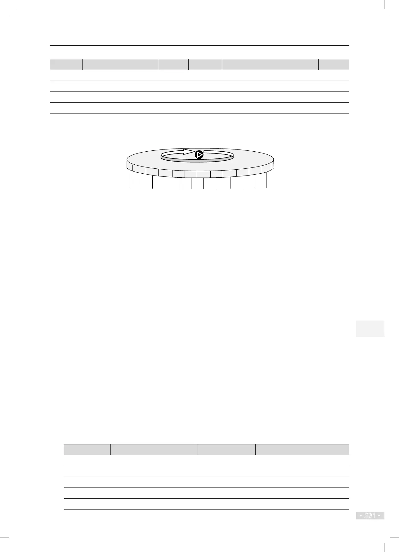
Figure 8-15 Shift between parameters displayed in the stop state
Bus voltage
Input terminal
low bits
Input terminal
high bits
Output terminal
Current floor
Current position
Car load
Slow-down distance
at rated speed
CTB output state
System state
Set speed
CTB input state
Shift between parameters
displayed in the stop state
Bit0 Bit1 Bit2 Bit3 Bit4 Bit5 Bit6 Bit7 Bit8 Bit9 Bit10 Bit11
The running and stop parameters of the NICE3000
new
system are the important references for engineers to
perform commissioning on site. The parameters are described as follows:
1. Running speed: indicates the actual running speed of the elevator.
Its maximum value is F0-03 (Maximum running speed), in unit of m/s.
2. Set speed: indicates the set speed of the NICE3000
new
system during elevator running. It is
the running speed calculated by the system theoretically at which the elevator should run. Its
unit is m/s.
3. Bus voltage: indicates the DC bus voltage of the NICE3000
new
system, in unit of m/s.
4. Output voltage: indicates the effective value of the equivalent voltage of the PWM wave
output by the NICE3000
new
system, in unit of V.
5. Output current: indicates the effective value of the actual current when the NICE3000
new
system drives the motor to turn, in unit of A.
6. Output frequency: indicates the actual frequency of the motor during running. It has a xed
corresponding relationship with the running speed. The unit is Hz.
7. Input terminal low bits: indicate the signal states of input terminals by bit.
A total of 16 bits are dened as below:
Bit Meaning Bit Meaning
Bit0 Reserved Bit8 Inspection signal
Bit1 Up leveling signal Bit9 Inspection up signal
Bit2
Down leveling signal
Bit10
Inspection down signal
Bit3 Door zone signal Bit11 Fire emergency signal
Bit4 Safety circuit feedback 1 Bit12 Up limit signal