NICE3000
new
User Manual
3 Mechanical and Electrical Installation
- 39 -
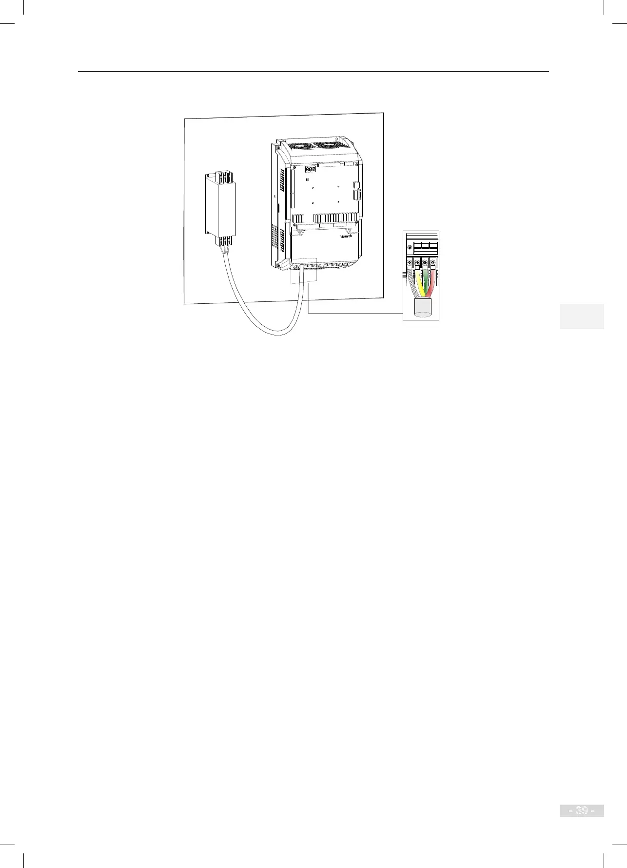
Figure 3-14 Installing lter and controller on the conductive plane
3) DC bus terminals (+), (-)
● Terminals (+) and (-) of the DC bus have residual voltage after the controller is switched off.
Wait at least 10 minutes and ensure that the voltage is lower than 36 VAC before performing
wiring. Failure to comply may result in electric shock
● When connecting external braking components for the controller of 37 kW and above, never
reverse (+) and (-). Failure to comply may result in damage to the controller and even cause a
re.
● The cable length of the braking unit must not exceed 10 m. Use the twisted pair wire or tight
pair wires for parallel connection.
● Do not connect the regen. resistor directly to the DC bus. Otherwise, it may damage the
controller and even cause a re.
4) Terminals(+), PB for connecting regen. resistor
● These terminals are valid only for the models below 37 kW that have the built-in braking unit.
● Connect a regen. resistor of the recommended model, and ensure that the cable length of the
regen. resistor is shorter than 5 m. Otherwise, it may damage the controller.
5) Controller output terminals U, V, W
● The specication and installation method of external power cables must comply with the local
safety regulations and related IEC standards.
● Use copper conductors of a proper size as power cables according to the recommended values
in Table 4-2.
● Do not connect a capacitor or surge absorber to the output side of the controller. Otherwise, it
may cause frequent controller trips or even damage the controller.
● If the motor cable is too long, electrical resonance will be generated due to the impact of
distributed capacitance. This will damage the motor insulation or generate higher leakage