3 Mechanical and Electrical Installation NICE3000
new
User Manual
- 40 -
current, causing the controller to trip in overcurrent protection. If the motor cable is greater than
100 m long, an AC output reactor must be installed close to the controller.
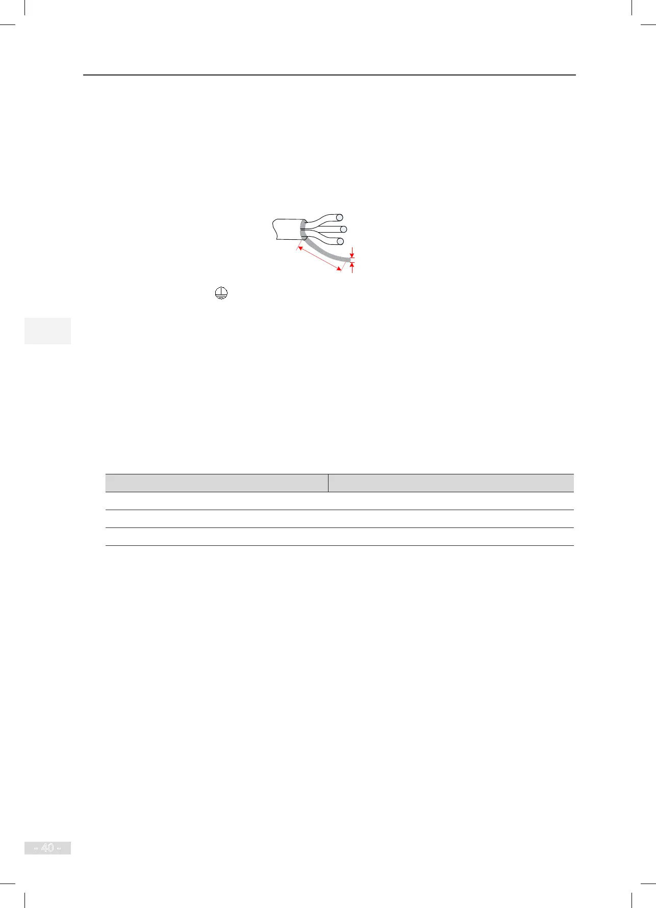
● Use the shielded cable as the output power cables, with the shield connected to the grounding
cable.
● The lead-out cable by the shield must be as short as possible, with the width smaller than 1/5
of the length.
6) Grounding terminal (PE)
● The grounding terminal of the main circuit must be tied to the ground reliably with the grounding
resistance of the cable smaller than 10 Ω. Otherwise, the controller may be abnormal or dam-
aged.
● Do not connect this terminal to the neutral conductor of the power supply.
● The impedance of the PE conductor must be able to withstand the large short circuit current
that may arise when a fault occurs.
● Select the size of the PE conductor according to the following table:
Table 3-3 Size of PE conductor
Cross-sectional Area of a Phase Conductor (S) Min. Cross-sectional Area of Protective Conductor (Sp)
S ≤ 16 mm
2
S
16 mm
2
< S ≤ 35 mm
2
16 mm
2
35 mm
2
< S S/2
● Use a yellow/green cable as the PE conductor.
● It is recommended that the controller be installed on the conductive metal plane. Ensure that
the entire conductive back of the controller is in good contact with the installation plane.
● Install the lter and controller on the same plane to ensure the ltering effect of the lter.
6) Upstream protection device
● Install a proper protection device on the power input side to provide protections on overcurrent,
short circuit and electrical isolation.
● When selecting the protection device, consider the current capacity of the power cable, system
overload capacity and short circuit capacity of upstream power distribution. Generally, make
selection according to the recommended values in Table 4-1.