NICE3000
new
User Manual
3 Mechanical and Electrical Installation
- 55 -
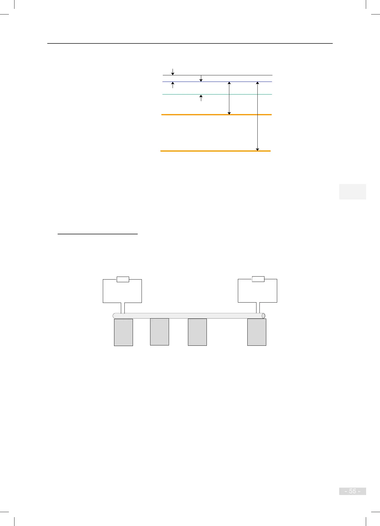
Figure 3-30 RS485 cabling diagram
RS485 bus
PE
R, S, T power cables
U, V, W motor cables
> 5 cm
> 20 cm
> 50 cm
Backplane of cabinet
> 1 cm
● The distance between the RS485 bus and strong-current cables must be larger than 20 cm.
● The distance between the RS485 bus and U, V, W motor cables must be larger than 50 cm.
● The distance between the RS485 bus and grounding cable must be larger than 5 cm.
● The distance between the RS485 bus and the backplane of the control cabinet must be larger
than 1 cm.
◆
Problems and Handling
Problem 1: Termination resistor connection
Figure 3-31 Correct termination resistor connection diagram
Host 1
Node 3 Node N
120
Ω
Node 2
RS485 bus
…
120
Ω
1. The termination resistor can be connected only at two ends of the bus.
When the resistance of the RS485 bus measured by the multimeter is about 60 Ω (all devices must power
off during measurement), the bus is normal. If the measured resistance is lower than 50 Ω, check two
ends of the bus, and check whether another resistor is added; if yes, disconnect this one. If the measured
resistance is 0 Ω, check whether short circuit exists or a node is damaged.