NICE3000
new
User Manual
4 Peripheral Devices and Options
- 71 -
1. The preceding conguration takes the synchronous motor as an example. The asynchronous
motor has poor energy transfer efciency, and you can reduce the power of the regen. resistor or
increase the resistance of the regen. resistor.
2. It is recommended that you select the regen. resistor closest to the minimum resistance.
3. "x 2" indicates that two sets are required. Take NICE-L-C-4110 as an example: "9 x 2, 18000 x 2,
MDBUN-90-T x 2" indicates that two sets of (9 Ω, 15000 W) regen. resistor + MDBUN-90-T braking
unit are connected in parallel to the controller. "x 3" indicates that three sets are required.
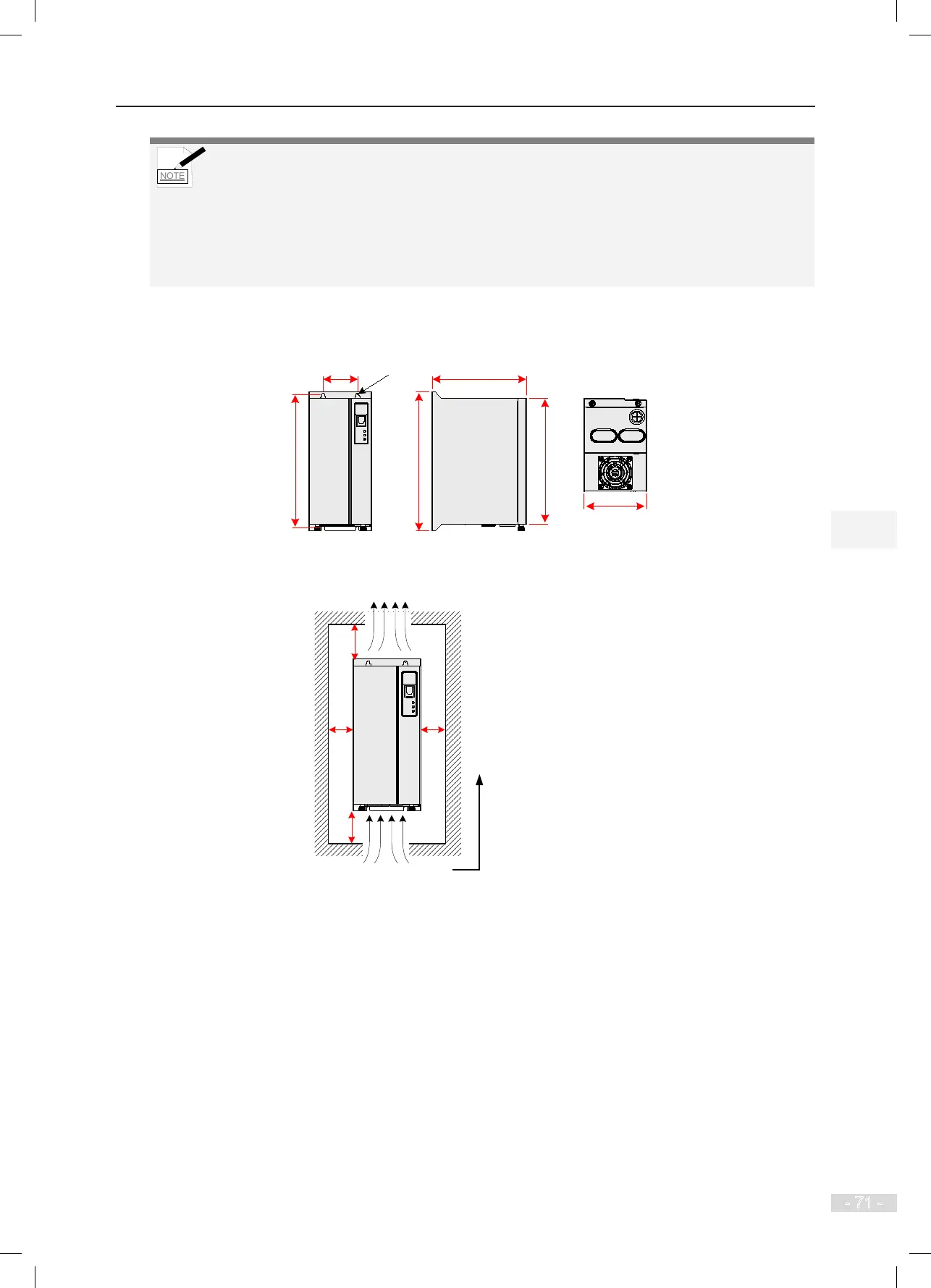
2. Mounting dimensions
Figure 4-2 Mounting dimensions of the braking unit
φ5
60
236
247
165
224
110
Unit: mm
Figure 4-3 Clearance around the braking unit for mounting
Hot air
Cold air
100
50 50
100
The braking unit should be
mounted vertically upward.
For use and installation of the MDBUN series braking unit, refer to the MDBUN Series Braking Unit
User Manual.