4 Peripheral Devices and Options NICE3000
new
User Manual
- 82 -
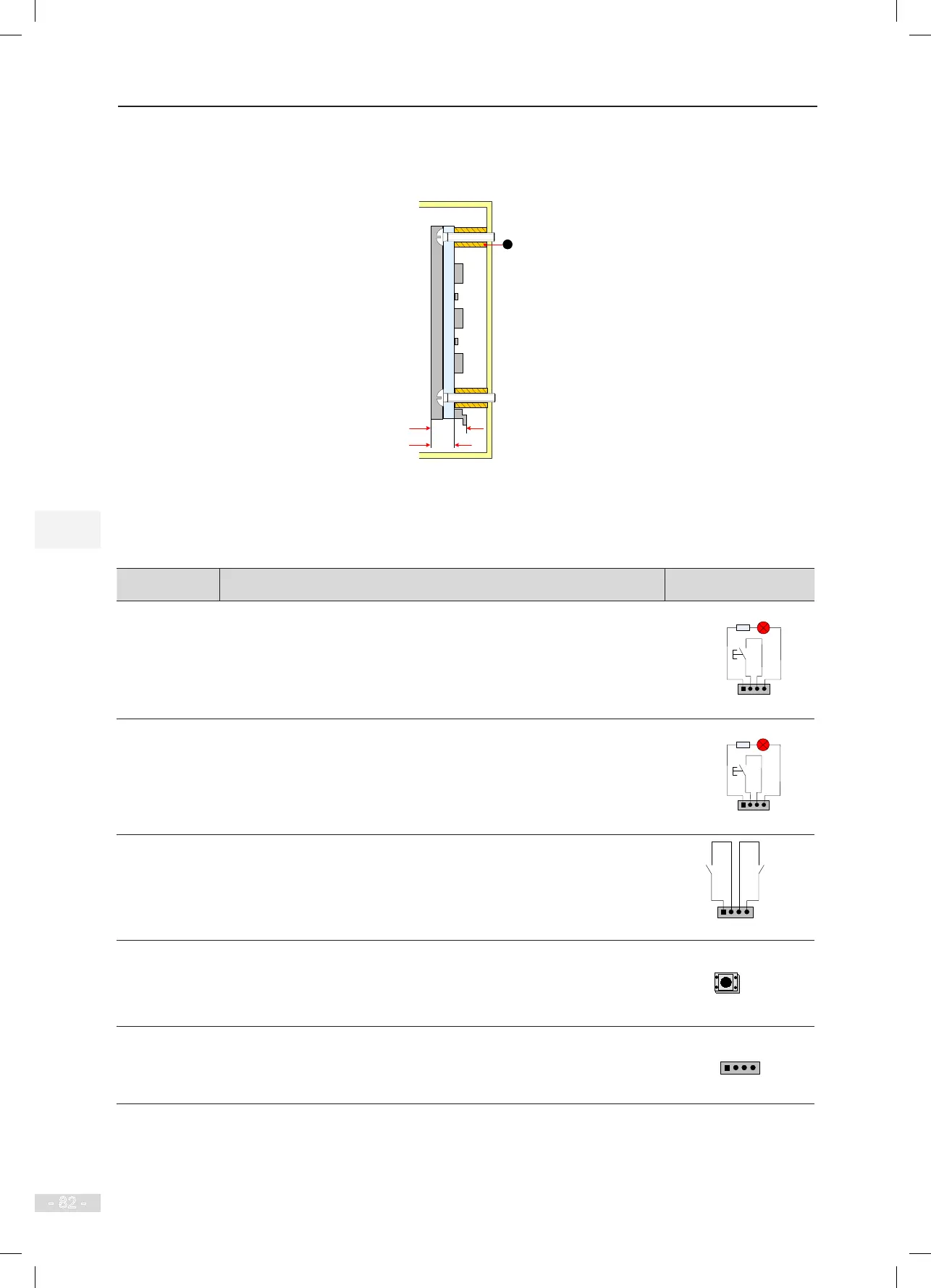
The following gure shows the installation method of HCB-U1.
Figure 4-15 Installation method of HCB-U1
9.4
15
Unit: mm
MCTC-HCB-U1
1 - Plastic support higher than 1 cm
2 - Self-tapping screw 4-φ4.9x30
1
The following table describes the input and output terminals of HCB-U1.
Table 4-12 Input and output terminals of HCB-U1
Terminal Name Function Terminal Wiring
J1
Interface for the up call button and indicator
Pins 2 and 3 are for up call input. Pins 1 and 4 are power supply for the
up call indicator (24 VDC output, load capacity: 40 mA).
1 2 3 4
Up call indicator
Up call
button
J2
Interface for the down call button and indicator
Pins 2 and 3 are for down call input. Pins 1 and 4 are power supply for
the down call indicator (24 VDC output, load capacity: 40 mA).
1 2 3 4
Down call indicator
Down call
button
J3
Interface for the re emergency and elevator lock switches
Pins 1 and 2 are for elevator lock input. Pins 3 and 4 are for re
emergency input.
1 2 3 4
Fire
emergency
input
Elevator
lock input
S1
Button for setting the oor address.
Hold down the button to adjust the oor address (range: 0−56). After you
stop pressing, the address number blinks three times, and therefore the
setting is successful.
CN1
Modbus communication and power supply terminal
Pins 2 and 3 are for Modbus communication. Pins 1 and 4 are for DC
power supply.