Moog Animatics SmartMotor™ Developer's Guide,Rev. L
Page 84 of 909
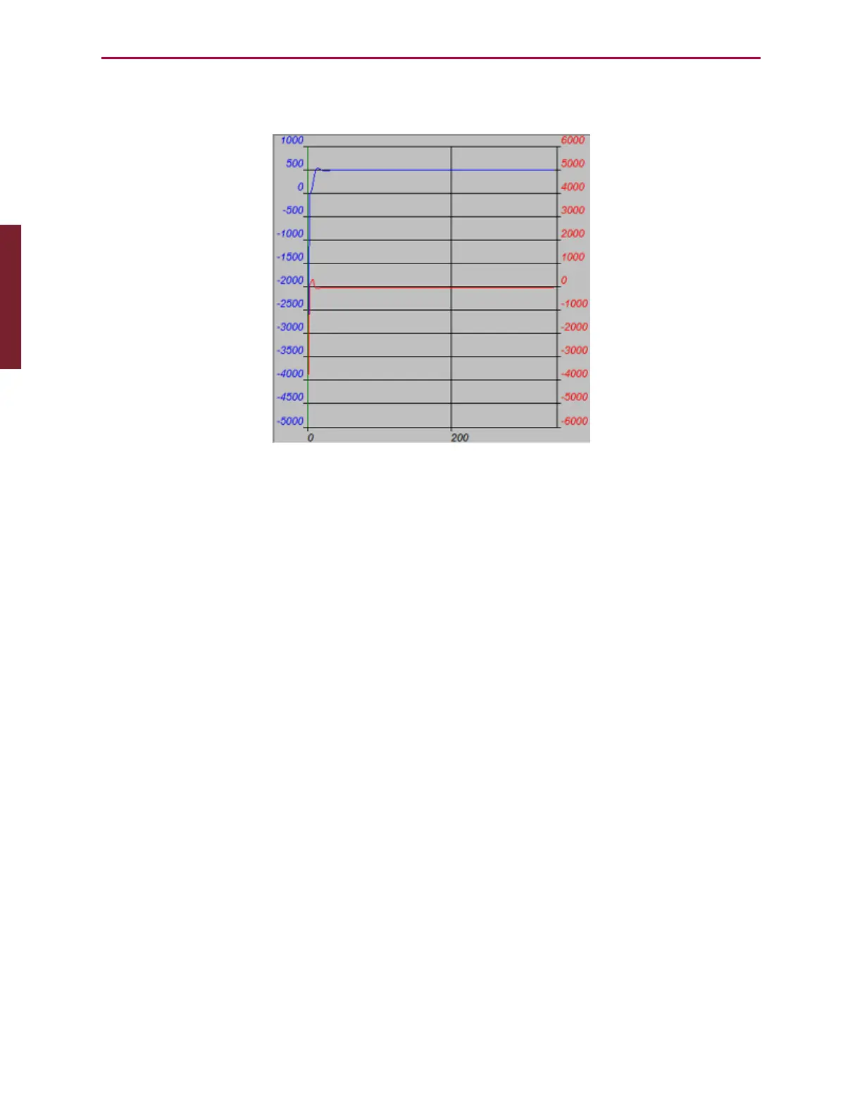
If the SmartMotor is connected, is on and is still, you should see results similar to those in the
following figure.
Sample Step Response
The upper curve with the legend on the left is the SmartMotor’s actual position over time.
Notice that it overshot its target position before settling in. Adjusting the PID Tuning will
stiffen the motor up and create less overshoot. For details, see Tuning and PIDControl on
page 231. In a real-world application, there will be an acceleration profile, not a demand for
instantaneous displacement, so significant overshoot will not exist. Nevertheless, it is useful
to look at the worst-case scenario of a step response.
To try a different set of tuning parameters, select the Tuning Values tab to the left of the
graph area. As shown in the following figure, you will see a list of tuning parameters with two
columns: the left column lists what is currently in the SmartMotor; the right column provides
an area to make changes.
Part 1: Programming: Tuner